Proposed Chapter 11 for North Carolina Residential Code. Revised December 3 , 2010
Part II---Definitions
CHAPTER 2
DEFINITIONS
SECTION R202
DEFINITIONS
Note: Following are definitions that need to be synchronized with the energy code. First are a set of simple
additions that are now referenced in Chapter 11. The second list contains modifications to existing definitions.
Additional definitions:
ACH50. Air Changes per Hour of measured air flow in relation to the building volume while the
building is maintained at a pressure difference of 50 Pascals.
AIR BARRIER MATERIAL. Material(s) that have an air permeability not to exceed 0.004 cfm/ft2
under a pressure differential of 0.3 in. water (1.57psf) (0.02 L/s.m2 @ 75 Pa) when tested in
accordance with ASTM E 2178.
AIR BARRIER SYSTEM. Material(s) assembled and joined together to provide a barrier to air
leakage through the building envelope. An air barrier system is a combination of air barrier
materials and sealants.
BPI ENVELOPE PROFESSIONAL. An individual that has successfully passed the Building
Performance Institute written and field examination requirements for the Building Envelope
certification.
CFM25. Cubic Feet per Minute of measured air flow while the forced air system is maintained at
a pressure difference of 25 Pascals (0.1 inches w.p.)
CFM50. Cubic Feet per Minute of measured air flow while the building is maintained at a
pressure difference of 50 Pascals (0.2 inches w.p.).
CODE OFFICIAL. The officer or other designated authority charged with the administration and
enforcement of this code, or a duly authorized representative.
F-FACTOR. The perimeter heat loss factor for slab-on-grade floors (Btu/h x ft x °F) [W/(m x K)].
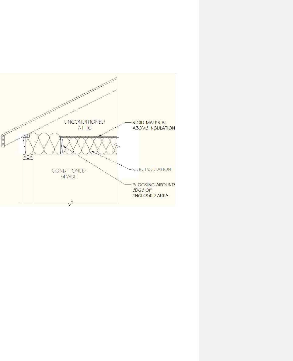
FULLY ENCLOSED ATTIC FLOOR SYSTEM– The ceiling insulation is enclosed on all six
sides by an air barrier system, such as taped drywall below, solid framing joists on the sides,
solid blocking on the ends, and solid sheathing on top which totally enclose the insulation. This
system provides for full depth insulation over the exterior walls.
HEAT TRAP. An arrangement of piping and fittings, such as elbows, or a commercially
available heat trap that prevents thermosyphoning of hot water during standby periods.
HEATED SLAB. Slab-on-grade construction in which the heating elements, hydronic tubing, or
hot air distribution system is in contact with, or placed within or under, the slab.
HERS RATER. An individual that has completed training and been certified by RESNET
(Residential Energy Services Network) Accredited Rating Provider.
HUMIDISTAT. A regulatory device, actuated by changes in humidity, used for automatic control
of relative humidity.
INFILTRATION. The uncontrolled inward air leakage into a building caused by the pressure
effects of wind or the effect of differences in the indoor and outdoor air density or both.

READILY ACCESSIBLE. Capable of being reached quickly for operation, renewal or inspection
without requiring those to whom ready access is requisite to climb over or remove obstacles or
to resort to portable ladders or access equipment (see “Accessible”).
LAMP. The device in a lighting fixture that provides illumination, typically a bulb, fluorescent
tube, or light emitting diode (LED).
SCREW LAMP HOLDERS. A lamp base that requires a screw-in-type lamp, such as a
compact-fluorescent, incandescent, or tungsten-halogen bulb.
SEMI-CONDITIONED SPACE A space indirectly conditioned within the thermal envelope that
is not directly heated or cooled. For energy purposes, semi-conditioned spaces are treated as
conditioned spaces.
SERVICE WATER HEATING. Supply of hot water for purposes other than comfort heating.
WALL, ABOVE-GRADE A wall more than 50 percent above grade and enclosing conditioned
space. This includes between-floor spandrels, peripheral edges of floors, roof and basement
knee walls, dormer walls, gable end walls, walls enclosing a mansard roof and skylight shafts.
WALL, CRAWL SPACE. The opaque portion of a wall that encloses a crawl space and is
partially or totally below grade.
ZONE. A space or group of spaces within a building with heating or cooling requirements that
are sufficiently similar so that desired conditions can be maintained throughout using a single
controlling device.
Modified or updated definitions:
Original:
ACCESSIBLE. Signifies access that requires the removal of an access panel or similar
removable obstruction.
Modified:
ACCESSIBLE. Signifies access that requires the removal of an access panel or similar
removable obstruction. For energy purposes, ACCESSIBLE means admitting close approach
as a result of not being guarded by locked doors, elevation or other effective means (see
“Readily accessible”).
Original:
ADDITION. An extension or increase in floor area or height of a building or structure.
Modified:
ADDITION. An extension or increase in floor area or height of a building or structure. For
energy purposes, an extension or increase in the conditioned space floor area or height of a
building or structure.
Original:
BASEMENT WALL. The opaque portion of a wall that encloses one side of a basement and
has an average below grade wall area that is 50% or more of the total opaque and non-opaque
area of that enclosing side.
Modified:
BASEMENT WALL. The opaque portion of a wall that encloses one side of a basement and
has an average below grade wall area that is 50% or more of the total opaque and non-opaque
area of that enclosing side. For energy purposes, a wall 50 percent or more below grade and
enclosing conditioned space.
Original:
BUILDING THERMAL ENVELOPE. The basement walls, exterior walls, floor, roof, and any
other building elements that enclose conditioned spaces.

Modified:
BUILDING THERMAL ENVELOPE. The basement walls, exterior walls, floor, roof, and any
other building element that enclose conditioned space. This boundary also includes the
boundary between conditioned space and any exempt or unconditioned space.
Original:
LABELED. Equipment, materials or products to which have been affixed a label, seal, symbol
or other identifying mark of a nationally recognized testing laboratory, inspection agency, or
other organization as approved by the NC Building Code Council concerned with product
evaluation that maintains periodic inspection of the production of the above-labeled items and
whose labeling indicates either that the equipment, material or product meets identified
standards or has been tested and found suitable for a specified purpose.
Modified:
LABELED. Appliances, Equipment, materials or products to which have been affixed a label,
seal, symbol or other identifying mark of a nationally recognized testing laboratory, inspection
agency, or other organization as approved by the NC Building Code Council concerned with
product evaluation that maintains periodic inspection of the production of the above-labeled
items and whose labeling indicates either that the appliance, equipment, material or product
meets identified standards or has been tested and found suitable for a specified purpose.
Original:
R-VALUE (THERMAL RESISTANCE). The inverse of the time rate of heat flow through a
building thermal envelope element from one of its bounding surfaces to the other for a unit
temperature difference between the two surfaces, under steady state conditions, per unit area
(h x ft
2
x °F/Btu).
Modified:
R-VALUE (THERMAL RESISTANCE). The inverse of the time rate of heat flow through a body
from one of its bounding surfaces to the other surface for a unit temperature difference between
the two surfaces, under steady state conditions, per unit area (h x ft
2
x °F/Btu) [(m
2
x K)/W].
Original:
SOLAR HEAT GAIN COEFFICIENT (SHGC). The solar heat gain through a fenestration or
glazing assembly relative to the incident solar radiation (Btu/h x ft
2
x °F)
Modified:
SOLAR HEAT GAIN COEFFICIENT (SHGC). The ratio of the solar heat gain entering the
space through the fenestration assembly to the incident solar radiation. Solar heat gain includes
directly transmitted solar heat and absorbed solar radiation which is then reradiated, conducted
or convected into the space. This value is related to the Shading Coefficient (SC) by the
formula SHGC = 0.87 * SC.
Part IV---Energy Conservation
CHAPTER 11
ENERGY EFFICIENCY
SECTION N1101
SCOPE, GENERAL REQUIREMENTS, AND
ADDITIONAL DEFINITIONS
N1101.1 Scope. This chapter shall regulate the
design and construction of buildings for the effective
use of energy. This code is intended to provide
flexibility to permit the use of innovative approaches
and techniques to achieve the effective use of energy.
This code is not intended to prevent the use of any
material, method of construction, design or insulating
system not specifically prescribed herein, provided
that such construction, design or insulating system
has been approved by the code official as meeting the
intent of this code.
This code is not intended to abridge safety, health or
environmental requirements contained in other
applicable codes or ordinances.
Exception: Portions of the building envelope that do
not enclose conditioned space.
N1101.1.2 Existing buildings. Except as specified in
this chapter, this code shall not be used to require the
removal, alteration or abandonment of, nor prevent
the continued use and maintenance of, an existing
building or building system lawfully in existence at
the time of adoption of this code.
N1101.1.3 Additions, alterations, renovations or
repairs. Additions, alterations, renovations or repairs
to an existing building, building system or portion
thereof shall conform to the provisions of this code as
they relate to new construction without requiring the
unaltered portion(s) of the existing building or
building system to comply with this code. Additions,
alterations, renovations or repairs shall not create an
unsafe or hazardous condition or overload existing
building systems. An addition shall be deemed to
comply with this code if the addition alone complies
or if the existing building and addition comply with
this code as a single building.
Exception:
1. The following need not comply provided the
energy use of the building is not increased:
a) Storm windows installed over existing
fenestration.
b) Incidental repairs requiring a new sash
or new glazing.
c) Existing ceiling, wall or floor cavities
exposed during construction provided
that these cavities are filled with
insulation.
d) Construction where the existing roof,
wall or floor cavity is not exposed.
2. Converting unconditioned attic space to
conditioned attic space. Ceilings shall be
insulated to a minimum of R-30, walls shall
be insulated to the exterior wall
requirements in Table N1102.1 and follow
backing requirements in Section
N1102.2.12.
N1101.2 Compliance. Compliance shall be
demonstrated by either meeting the requirements of
the North Carolina Energy Conservation Code or
meeting the requirements of this chapter. Climate
zones from Figures N1101.2(1), Figure N1101.2(2)
or Table N1101.2 shall be used in determining the
applicable requirements from this chapter. Projects
shall comply with Sections N1101, N1102.4,
N1102.5, and N1103.1, N1103.2.2, N1103.2.3, and
N1103.3 through N1103.9 and either:
1. Sections N1102.1 through N1102.3,
N1103.2.1 and N1104.1; or
2. North Carolina specific REScheck shall be
permitted to demonstrate compliance with
this code. Envelope requirements may not
be traded off against the use of high
efficiency heating and/or cooling equipment.
No trade-off calculations are needed for
required termite inspection and treatment
gaps.
N1101.2.1 Warm humid counties. Warm humid
counties are identified in Table N1101.2 by an
asterisk.
N1101.2.2 Change in space conditioning. Any
nonconditioned space that is altered to become
conditioned space shall be required to be brought into
full compliance with this code.

Exception:
Existing enclosed ceiling, wall or floor cavities
comply provided that these cavities are filled
with insulation.
N1101.3 Identification. Materials, systems and
equipment shall be identified in a manner that will
allow a determination of compliance with the
applicable provisions of this chapter.
N1101.4 Building thermal envelope insulation. An
R-value identification mark shall be applied by the
manufacturer to each piece of building thermal
envelope insulation 12 inches (305 mm) or greater in
width. Alternately, the insulation installers shall
provide a certification listing the type, manufacturer
and R-value of insulation installed in each element of
the building thermal envelope. For blown or sprayed
insulation (fiberglass and cellulose), the initial
installed thickness, settled thickness, settled R-value,
installed density, coverage area and number of bags
installed shall be listed on the certification. For
sprayed polyurethane foam (SPF) insulation, the
installed thickness of the areas covered and R-value
of installed thickness shall be listed on the
certification. The insulation installer shall sign, date
and post the certification in a conspicuous location on
the job site.
N1101.4.1 Blown or sprayed roof/ceiling
insulation. The thickness of blown-in or sprayed
roof/ceiling insulation (fiberglass or cellulose) shall
be written in inches (mm) on markers that are
installed at least one for every 300 square feet (28
m2) throughout the attic space. The markers shall be
affixed to the trusses or joists and marked with the
minimum initial installed thickness with numbers a
minimum of 1 inch (25 mm) in height. Each
polyurethane foam thickness and installed R-value
shall be listed on certification provided by the
insulation installer.
N1101.4.2 Insulation mark installation. Insulating
materials shall be installed such that the
manufacturer’s R-value mark is readily observable
upon inspection.
N1101.5 Fenestration product rating. U-factors of
fenestration products (windows, doors and skylights)
shall be determined in accordance with NFRC 100 by
an accredited, independent laboratory, and labeled
and certified by the manufacturer. Products lacking
such a labeled U-factor shall be assigned a default U-
factor from Tables N1101.5(1) or N1101.5(2). The
solar heat gain coefficient (SHGC) of glazed
fenestration products (windows, glazed doors and
skylights) shall be determined in accordance with
NFRC 200 by an accredited, independent laboratory,
and labeled and certified by the manufacturer.
Products lacking such a labeled SHGC shall be
assigned a default SHGC from Table N1101.5(3).
N1101.6 Insulation product rating. The thermal
resistance (R-value) of insulation shall be determined
in accordance with the U.S. Federal Trade
Commission R-value rule (CFR Title 16, Part 460,
May 31, 2005) in units of h x ft2 x °F/Btu at a mean
temperature of 75°F (24°C).
N1101.7 Installation. All materials, systems and
equipment shall be installed in accordance with the
manufacturer’s installation instructions and this code.
N1101.7.1 Protection of exposed
foundation insulation. Insulation applied to
the exterior of basement walls, crawlspace
walls and the perimeter of slab-on-grade
floors shall have a rigid, opaque and
weather-resistant protective covering to
prevent the degradation of the insulation’s
thermal performance. The protective
covering shall cover the exposed exterior
insulation and extend a minimum of 6
inches (153 mm) below grade.
N1101.8 Above code programs.
Deleted
N1101.9 Certificate. A permanent certificate shall be
posted on or in the electrical distribution panel, in the
attic next to the attic insulation card, or inside a
kitchen cabinet or other approved location. The
certificate shall not cover or obstruct the visibility of
the circuit directory label, service disconnect label or
other required labels. The builder, permit holder, or
registered design professional shall be responsible for
completing the certificate. The certificate shall list
the predominant R-values of insulation installed in or
on ceiling/roof, walls, foundation (slab, basement
wall, crawlspace wall and/or floor) and ducts outside
conditioned spaces; U-factors for fenestration and the
solar heat gain coefficient (SHGC) of fenestration.
Where there is more than one value for each
component, the certificate shall list the value
covering the largest area. The certificate shall
indicate whether the building air leakage was visually
inspected as required in N1102.4.2.1 or provide
results of the air leakage testing required in
N1102.4.2.2 The certificate shall provide results of
duct leakage test required in N1102.4.2.2. Appendix
E-1 contains a sample certificate.

N1101.10 Additional Voluntary Criteria for
Increasing Residential Energy Efficiency.
Appendix E-4 contains additional voluntary measures
for increasing residential energy efficiency beyond
code minimums. Implementation of the increased
energy efficiency measures is strictly voluntary at the
option of the permit holder. The sole purpose of the
appendix is to provide guidance for achieving
additional residential energy efficiency
improvements that have been evaluated to be those
that are most cost effective for achieving an
additional 15-20% improvement in energy efficiency
beyond code minimums.
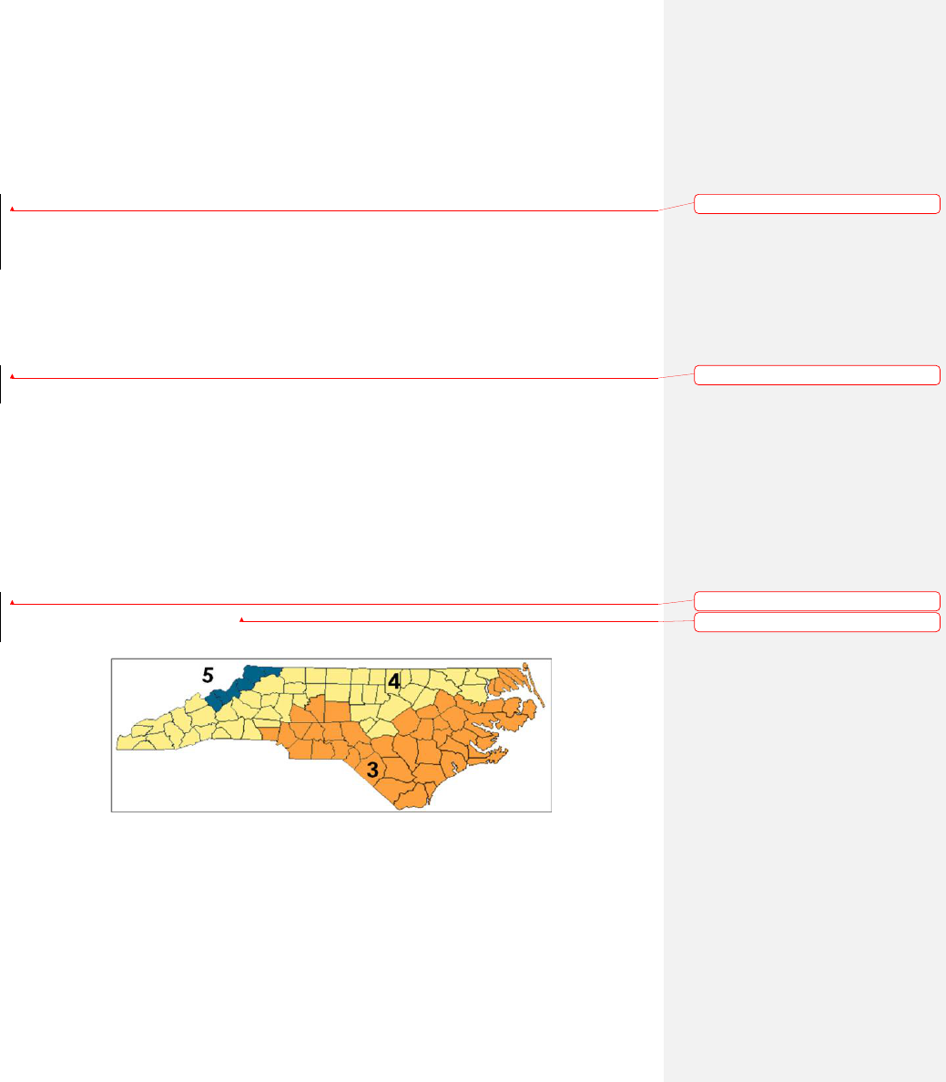
TABLE N1101.2
NORTH CAROLINA CLIMATE ZONES, MOISTURE REGIMES, AND WARM-HUMID DESIGNATIONS
BY COUNTY
Key: A – Moist, B – Dry, C – Marine. Absence of moisture designation indicates moisture regime is irrelevant.
Asterisk (*) indicates a warm-humid location.
NORTH
CAROLINA
4A Alamance
4A Alexander
5A Alleghany
3A Anson
5A Ashe
5A Avery
3A Beaufort
4A Bertie
3A Bladen
3A Brunswick*
4A Buncombe
4A Burke
3A Cabarrus
4A Caldwell
3A Camden
3A Carteret*
4A Caswell
4A Catawba
4A Chatham
4A Cherokee
3A Chowan
4A Clay
4A Cleveland
3A Columbus*
3A Craven
3A Cumberland
3A Currituck
3A Dare
3A Davidson
4A Davie
3A Duplin
4A Durham
3A Edgecombe
4A Forsyth
4A Franklin
3A Gaston
4A Gates
4A Graham
4A Granville
3A Greene
4A Guilford
4A Halifax
4A Harnett
4A Haywood
4A Henderson
4A Hertford
3A Hoke
3A Hyde
4A Iredell
4A Jackson
3A Johnston
3A Jones
4A Lee
3A Lenoir
4A Lincoln
4A Macon
4A Madison
3A Martin
4A McDowell
3A Mecklenburg
5A Mitchell
3A Montgomery
3A Moore
4A Nash
3A New Hanover*
4A Northampton
3A Onslow*
4A Orange
3A Pamlico
3A Pasquotank
3A Pender*
3A Perquimans
4A Person
3A Pitt
4A Polk
3A Randolph
3A Richmond
3A Robeson
4A Rockingham
3A Rowan
4A Rutherford
3A Sampson
3A Scotland
3A Stanly
4A Stokes
4A Surry
4A Swain
4A Transylvania
3A Tyrrell
3A Union
4A Vance
4A Wake
4A Warren
3A Washington
5A Watauga
3A Wayne
4A Wilkes
3A Wilson
4A Yadkin
5A Yancey
Figure N1101.2(1) North Carolina Climate Zones
Formatted: English (U.S.)
Formatted: Portuguese (Brazil)
Formatted: Portuguese (Brazil)
Formatted: English (U.S.)
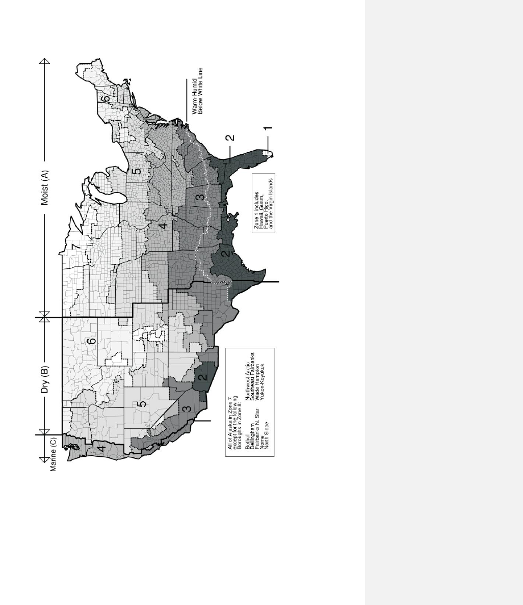
Figure N1101.2(2) Climate Zones
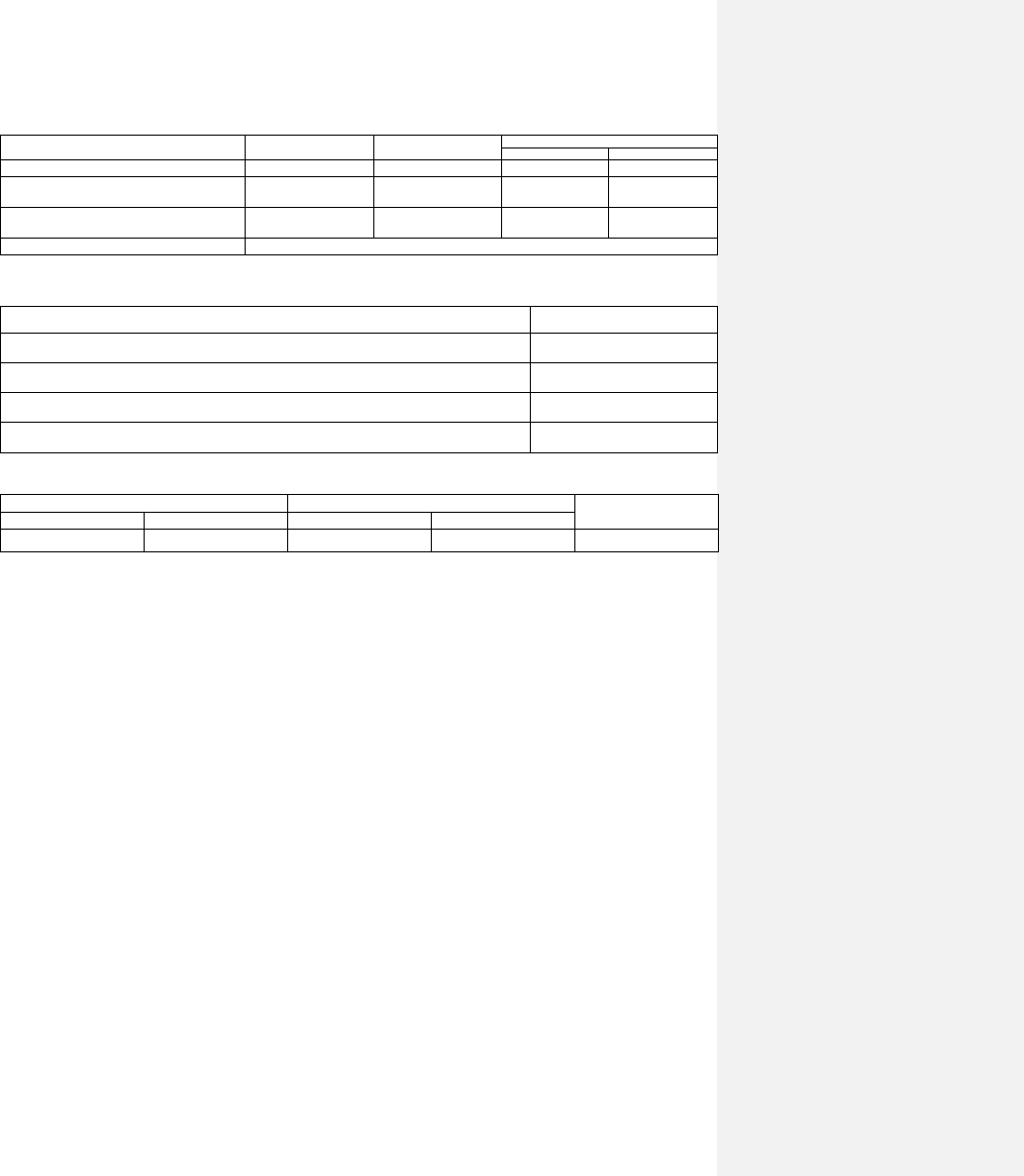
TABLE N1101.5(1)
DEFAULT GLAZED FENESTRATION U-FACTOR
FRAME TYPE
SINGLE
PANE
DOUBLE
PANE
SKYLIGHT
Single
Double
Metal
1.20
0.80
2.00
1.30
Metal with Thermal Break
1.10
0.65
1.90
1.10
Nonmetal or Metal Clad
0.95
0.55
1.75
1.05
Glazed Block
0.60
TABLE N1101.5(2)
DEFAULT DOOR U-FACTORS
DOOR TYPE
U-FACTOR
Uninsulated Metal
1.20
Insulated Metal
0.60
Wood
0.50
Insulated, nonmetal edge, max 45% glazing, any glazing double pane
0.35
TABLE N1101.5(3)
DEFAULT GLAZED FENESTRATION SHGC
SINGLE GLAZED
DOUBLE GLAZED
GLAZED BLOCK
Clear
Tinted
Clear
Tinted
0.8
0.7
0.7
0.6
0.6
SECTION N1102
BUILDING THERMAL ENVELOPE
N1102.1 Insulation and fenestration criteria. The
building thermal envelope shall meet the
requirements of Table N1102.1 based on the climate
zone specified in Table N1101.2.
N1102.1.1 R-value computation. Insulation material
used in layers, such as framing cavity insulation and
insulating sheathing, shall be summed to compute the
component R-value. The manufacturer’s settled R-
value shall be used for blown insulation.
Computed R-values shall not include an R-value for
other building materials or air films.
N1102.1.2 U-factor alternative. An assembly with a
U-factor equal to or less than that specified in Table
N1102.1.2 shall be permitted as an alternative to the
R-value in Table N1102.1.
N1102.1.3 Total UA alternative. If the total building
thermal envelope UA (sum of U-factor times
assembly area) is less than or equal to the total UA
resulting from using the U-factors in Table
N1102.1.2 (multiplied by the same assembly area as
in the proposed building), the building shall be
considered in compliance with Table N1102.1. The
UA calculation shall be done using a method
consistent with the ASHRAE Handbook of
Fundamentals and shall include the thermal bridging
effects of framing materials. The SHGC requirements
shall be met in addition to UA compliance.
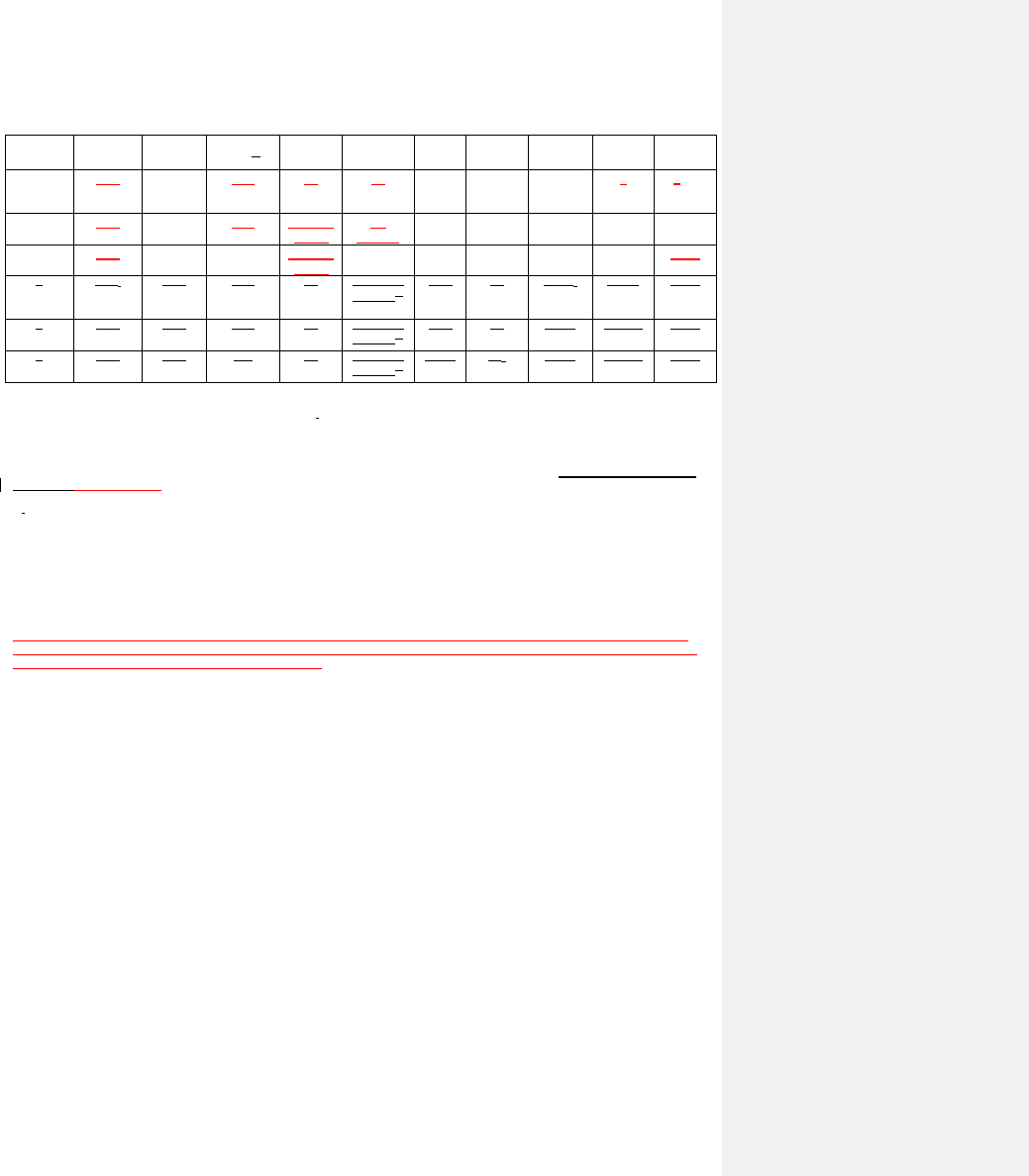
TABLE N1102.1
INSULATION AND FENESTRATION REQUIREMENTS BY COMPONENTa
CLIMATE
ZONE
FENESTRATIO
N
U-FACTORb
SKYLIGHTb
U-FACTOR
GLAZED
FENESTRATION
SHGCb, e
CEILING
R-VALUEk
WOOD
FRAME WALL
R-VALUE e
MASS
WALL
R-VALUEi
FLOOR
R-VALUE
BASEMENTc
WALL
R-VALUE
SLABd
R-VALUE
CRAWL
SPACEc
WALL
R-VALUE
3
0.35
0.65
0.30
30
13
5/10
19
10/13f
0
5/13
4
0.35
0.60
0.30
38 or 30
cont.
j
15,
13+2.5
h
5/10
19
10/13
10
d
10/13
5
0.35
0.60
NR
38 or 30
cont.
j
19, 13+5,
or 15+3
eh
13/17
30g
10/13
10
d
10/13
3
0.32j
0.65
0.27
42
19, 13+5,
or 15+3
eh
5/10
19
10/13f
5, 2 ft
10/13
4
0.32
0.60
0.27
42
19, 13+5,
or 15+3
eh
5/10
19
10/13
10, 2 ft
10/13
5
0.32
0.60
NR
42
19, 13+5,
or 15+3
eh
13/17
30g
10/13
10, 2 ft
15/19
For SI: 1 foot = 304.8 mm.
a. R-values are minimums. U-factors and SHGC are maximums.
b. The fenestration U-factor column excludes skylights. The SHGC column applies to all glazed fenestration.
c. ―10/13‖ means R-10 continuous insulated sheathing on the interior or exterior of the home or R-13 cavity insulation at the interior of the
basement wall or crawl space wall.
d. For monolithic slabs, insulation shall be applied from the inspection gap downward to the bottom of the footing or a maximum of 18 inches
below grade whichever is less. For floating slabs, insulation shall extend to the bottom of the foundation wall or 24 inches, whichever is less.
(See Appendix O) R-5 shall be added to the required slab edge R-values for heated slabs.
e. R -19 fiberglass batts compressed and installed in a nominal 2 × 6 framing cavity is deemed to comply. Fiberglass batts rated R-19 or higher
compressed and installed in a 2x4 wall is not deemed to comply.
f. Basement wall insulation is not required in warm-humid locations as defined by Figure N1101.2(1 and 2) and Table N1101.2.
g. Or insulation sufficient to fill the framing cavity, R-19 minimum.
h. ―13+5‖ means R-13 cavity insulation plus R-5 insulated sheathing. 15+3 means R-15 cavity insulation plus R-3 insulated sheathing. If
structural sheathing covers 25 percent or less of the exterior, insulating sheathing is not required where structural sheathing is used. If structural
sheathing covers more than 25 percent of exterior, structural sheathing shall be supplemented with insulated sheathing of at least R-2. 13+2.5
means R-13 cavity insulation plus R-2.5 sheathing.
i. For Mass Walls, the second R-value applies when more than half the insulation is on the interior of the mass wall.
j. R-30 shall be deemed to satisfy the ceiling insulation requirement wherever the full height of uncompressed R-30 insulation extends
over the wall top plate at the eaves. Otherwise R-38 insulation is required where adequate clearance exists or insulation must extend to
either the insulation baffle or within 1” of the attic roof deck.
k. Table value required except for roof edge where the space is limited by the pitch of the roof, there the insulation must fill the space up to the air
baffle.

N1102.2 Specific insulation requirements
N1102.2.1 Ceilings with attic spaces. Ceilings with
attic spaces over conditioned space shall meet the
insulation requirements in Table N1102.1.
Exceptions:
1) When insulation is installed in a fully
enclosed attic floor system, as described
in Appendix E 2.1, R-30 shall be
deemed compliant.
2) In roof edge and other miscellaneous
details such as bay windows,
dormers, and similar areas where the
space is limited, the insulation must
fill the space up to the air baffle.
N1102.2.2 Ceilings without attic spaces. Where the
design of the roof/ceiling assembly, including
cathedral ceilings, bay windows and other similar
miscellaneous areas, does not allow sufficient space
for the required insulation, the minimum required
insulation for such roof/ceiling assemblies shall be R-
30. This reduction of insulation from the
requirements of Section N1102.1 shall be limited to
500 square feet (46m
2
) of ceiling surface area. This
reduction shall not apply to the U-factor alternative
approach in Section N1102.1.2 and the total UA
alternative in Section N1102.1.3.
N1102.2.3 Access hatches and doors. Horizontal
access doors from conditioned spaces to
unconditioned spaces (e.g., attics and crawl spaces)
shall be weatherstripped and insulated to an R-10
minimum value, and vertical doors to such spaces
shall be weatherstripped and insulated to R-5.
Access shall be provided to all equipment that
prevents damaging or compressing the insulation. A
wood framed or equivalent baffle or retainer is
required to be provided when loose fill insulation is
installed, the purpose of which is to prevent the loose
fill insulation from spilling into the living space when
the attic access is opened, and to provide a permanent
means of maintaining the installed R-value of the
loose fill insulation.
Exceptions: 1) Pull down stair systems shall
be weatherstripped and insulated to an R-5
insulation value such that the insulation
does not interfere with proper operation
of the stair. Non-rigid insulation materials
are not allowed. Additional insulation
systems that enclose the stair system from
above are allowed. Exposed foam plastic
must meet the provisions of the North
Carolina Residential Code.
2) Full size doors that are part of the
building thermal envelope and provide a
passageway to unconditioned spaces shall
meet the requirements of exterior doors in
Section N1102.3.4.
N1102.2.4 Mass walls. Mass walls for the purposes
of this chapter shall be considered above-grade walls
of concrete block, concrete, insulated concrete form
(ICF), masonry cavity, brick (other than brick
veneer), earth (adobe, compressed earth block,
rammed earth) and solid timber/logs.
N1102.2.5 Steel-frame ceilings, walls, and floors.
Steel-frame ceilings, walls and floors shall meet the
insulation requirements of Table N1102.2.5 or shall
meet the U-factor requirements in Table N1102.1.2.
The calculation of the U-factor for a steel-frame
envelope assembly shall use a series-parallel path
calculation method.
N1102.2.6 Floors. Floor insulation shall be installed
to maintain permanent contact with the underside of
the subfloor decking. The distance between tension
support wires or other devices that hold the floor
insulation in place against the subfloor shall be no
more than 18 inches. In addition, supports shall be
located no further than 6 inches from each end of the
insulation.
Exception: Enclosed floor cavity such as
garage ceilings, cantilevers or buildings on
pilings with enclosed floor cavity with the
insulation fully in contact with the lower air
barrier. In this case, the band boards shall be
fully insulated to maintain thermal envelope
continuity.
N1102.2.7 Basement walls. Walls associated with
conditioned basements shall be insulated from the top
of the basement wall down to 10 feet (3048 mm)
below grade or to the basement floor, whichever is
less. Walls associated with unconditioned basements
shall meet this requirement unless the floor overhead
is insulated in accordance with Sections N1102.1 and
N1102.2.6.
N1102.2.8 Slab-on-grade floors. Slab-on-grade
floors with a floor surface less than 12 inches (305
mm) below grade shall be insulated in accordance
with Table N1102.1. The top edge of the insulation
installed between the exterior wall and the edge of
the interior slab shall be permitted to be cut at a 45-
degree (0.79 rad) angle away from the exterior wall.
Slab edge insulation shall have 2‖ termite inspection
gap consistent with Appendix O of this code.
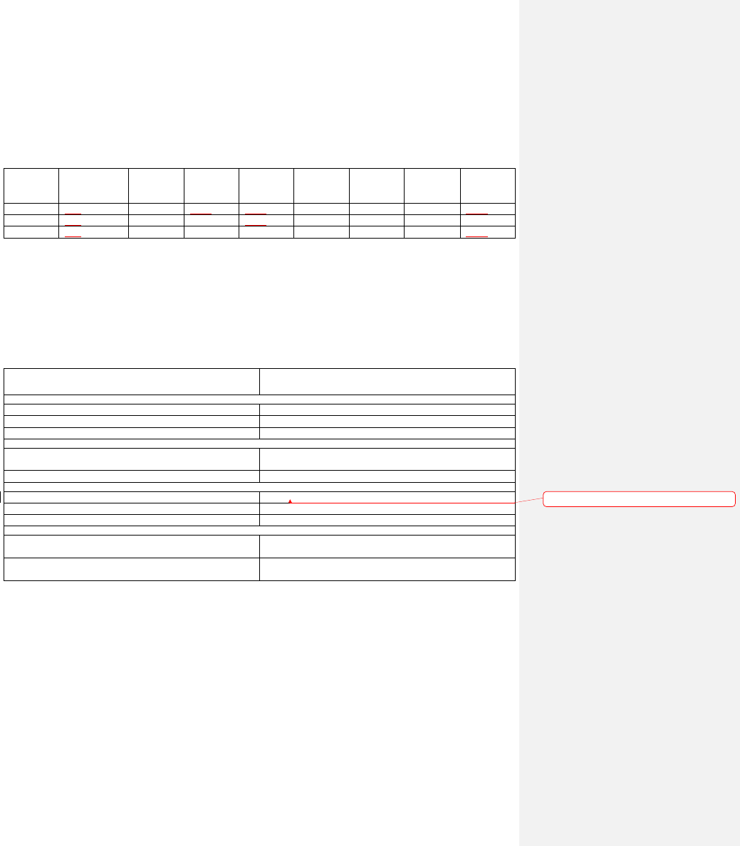
TABLE N1102.1.2
EQUIVALENT U-FACTORSa
CLIMATE
ZONE
FENESTRATION
U-FACTOR
SKYLIGHT
U-FACTOR
CEILING
U-FACTOR
FRAME
WALL
U-FACTOR
MASS
WALL
U-FACTORb
FLOOR
U-FACTOR
BASEMENT
WALL
U-FACTORd
CRAWL
SPACE
WALL
U-FACTORc
3
0.35
0.65
0.035
0.082
0.141
0.047
0.059
0.136
4
0.35
0.60
0.030
0.071
0.141
0.047
0.059
0.065
5
0.35
0.60
0.030
0.067
0.082
0.033
0.059
0.065
a. Nonfenestration U-factors shall be obtained from measurement, calculation or an approved source.
b. When more than half the insulation is on the interior, the mass wall U-factors shall be a maximum 0.12 in Zone 3, 0.10 in Zone 4, and the same
as the frame wall U-factor in Zone 5.
c. Basement wall U-factor of 0.360 in warm-humid locations as defined by Figures N1101.2(1), N1101.2(2) and Table N1101.2.
d. Foundation U-factor requirements shown in Table N1102.1.2 include wall construction and interior air films but exclude soil conductivity and
exterior air films. U-factors for determining code compliance in accordance with Section N1102.1.3 (total UA alternative) shall be modified to
include soil conductivity and exterior air films.
TABLE N1102.2.5
STEEL-FRAME CEILING, WALL AND FLOOR INSULATION
(R-VALUE)
WOOD FRAME
R-VALUE
REQUIREMENT
COLD-FORMED STEEL
EQUIVALENT R-VALUEa
Steel Truss Ceilingsb
R-30
R - 38 or R - 30 + 3 or R - 26 + 5
R-38
R - 49 or R - 38 + 3
R-49
R-38+5
Steel Joist Ceilingsb
R-30
R - 38 in 2×4 or 2×6 or 2×8
R - 49 in any framing
R-38
R - 49 in 2×4 or 2×6 or 2×8 or 2×10
Steel Framed Wall
R-13
R - 13 + 5 or R - 15 + 4 or R - 21 + 3 or R - 0 + 10
R-19
R - 13 + 9 or R - 19 + 8 or R - 25 + 7
R-21
R - 13 + 10 or R - 19 + 9 or R - 25 + 8
Steel Joist Floor
R-13
R - 19 in 2×6
R - 19 + 6 in 2×8 or 2×10
R-19
R - 19 + 6 in 2×6
R - 19 + 12 in 2×8 or 2×10
a. Cavity insulation R-value is listed first, followed by continuous insulation R-value.
b. Insulation exceeding the height of the framing shall cover the framing.
N1102.2.9 Closed crawl space walls.
Where the floor above a closed crawl space is not
insulated, the exterior crawlspace walls shall be
insulated in accordance with table 1102.1.
Wall insulation may be located in any combination of
the outside and inside wall surfaces and within the
structural cavities or materials of the wall system.
Wall insulation requires that the exterior wall band
joist area of the floor frame be insulated. Wall
insulation shall begin 3 inches (76.2mm) below the
top of the masonry foundation wall and shall extend
down to 3 inches (76.2mm) above the top of the
footing or concrete floor, 3 inches(76.2mm ) above
the interior ground surface or 24 inches (609.6mm)
below the outside finished ground level, whichever is
less. (See Appendix E-2.2 details)
Termite inspection, clearance, and wicking gaps are
allowed in wall insulation systems. Insulation may
be omitted in the gap area without energy penalty.
The allowable insulation gap widths are listed in
Table N1102.2.9. If gap width exceeds the
Formatted: Portuguese (Brazil)
allowances, one of the following energy compliance
options shall be met:
1. Wall insulation is not allowed and the required
insulation value shall be provided in the floor system.
2. Compliance shall be demonstrated with energy
trade-off methods provided by a North Carolina-
specific version of RESCHECK
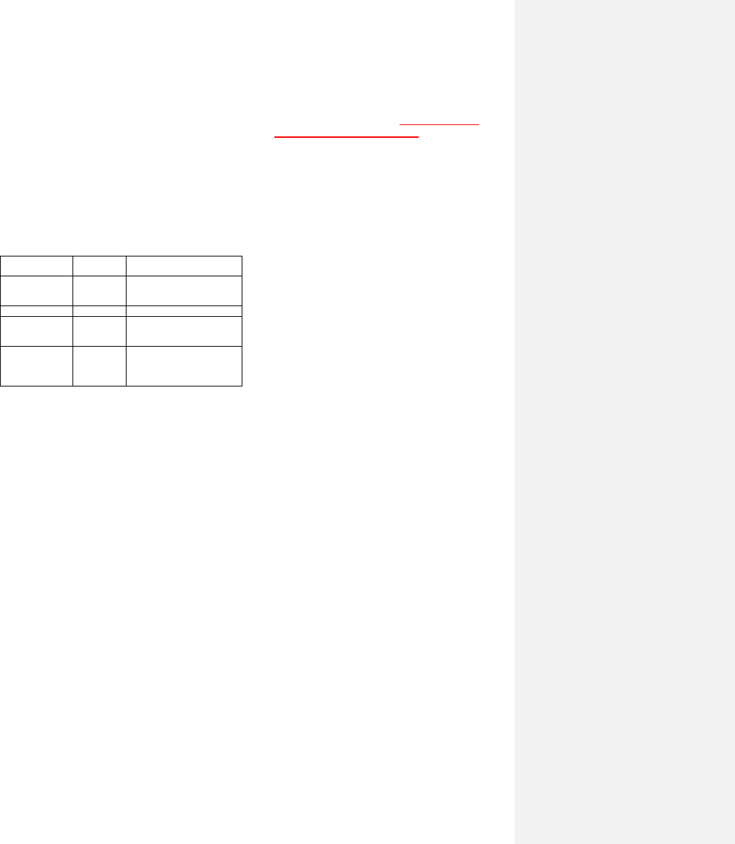
TABLE N1102.2.9
WALL INSULATION ALLOWANCES FOR TERMITE
TREATMENT AND INSULATION GAPS
Maximum Gap
Width(inches)
Insulation
Location
Gap Description
3
Outside
Above grade inspection
between top of insulation and
bottom of siding
6
Outside
Below grade treatment
4a
Inside
Wall inspection between top
of insulation and bottom of
sill
4a
Inside
Clearance / wicking space
between bottom of insulation
and top of ground surface,
footing, or concrete floor.
For si 1 inch = 25.4mm
a. No insulation shall be required on masonry wall of 9 inches in
height or less.
N1102.2.10 Masonry veneer. Insulation shall not be
required on the horizontal portion of the foundation
that supports a masonry veneer.
N1102.2.11 Thermally isolated conditioned
sunroom insulation. The minimum ceiling
insulation R-values shall be R-19 in Zones 3 and 4,
and R-24 in Zone 5. The minimum wall R-value shall
be R-13. New wall(s) separating a sunroom from
conditioned space shall meet the building thermal
envelope requirements. Floor and slab insulation
shall comply with values in Table N1102.1.1.
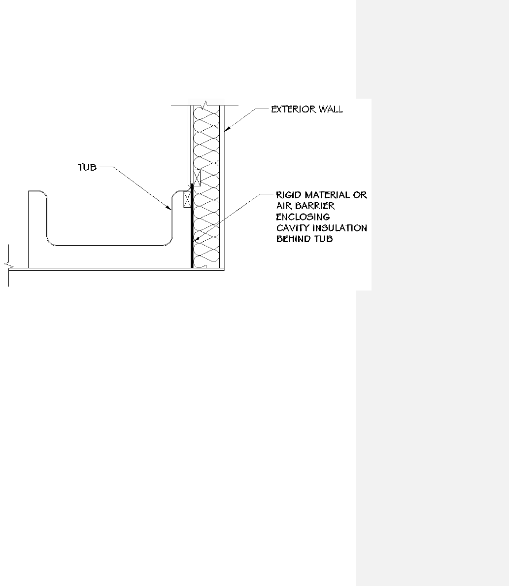
N1102.2.12 Framed cavity walls. The exterior
thermal envelope wall insulation shall be installed in
substantial contact and continuous alignment with the
building envelope air barrier. Insulation shall be
substantially free from installation gaps, voids, or
compression. For framed walls, the cavity insulation
shall be enclosed on all sides with a rigid material or
an air barrier material. Wall insulation shall be
enclosed at the following locations when installed on
exterior walls prior to being covered by subsequent
construction, consistent with the Appendix E-2.3 of
this code:
1. Tubs
2. Showers
3. Stairs
4. Fireplace units
Enclosure of wall cavity insulation also applies to
walls that adjoin attic spaces by placing a rigid
material or air barrier material on the attic space
side of the wall on the attic space side of the wall.
N1102.3 Fenestration.
N1102.3.1 U-factor. An area-weighted average of
fenestration products shall be permitted to satisfy the
U-factor requirements.
N1102.3.2 Glazed fenestration SHGC. An area-
weighted average of fenestration products more than
50 percent glazed shall be permitted to satisfy the
SHGC requirements.
N1102.3.3 Glazed fenestration exemption. Up to 15
square feet (1.4m
2
) of glazed fenestration per
dwelling unit shall be permitted to be exempt from
U-factor and SHGC requirements in Section
N1102.1. This exemption shall not apply to the U-
factor alternative approach in Section N1102.1.2 and
the Total UA alternative in Section N1102.1.3.
N1102.3.4 Opaque door. Opaque doors separating
conditioned and unconditioned space shall have a
maximum U-factor of 0.35.
Exception: One side-hinged opaque door
assembly up to 24 square feet (2.22 m2) in
area is exempted from the U-factor
requirement in Section N1102.1. This
exemption shall not apply to the U-factor
alternative approach in Section N1102.1.2
and the Total UA alternative in Section
N1102.1.3.
N1102.3.5 Thermally isolated conditioned
sunroom U-factor and SHGC. The maximum
fenestration U-factor shall be 0.40 and the maximum
skylight U-Factor shall be 0.75. Sunrooms with
cooling systems shall have a maximum fenestration
SHGC of 0.40 for all glazing.
New windows and doors separating the sunroom
from conditioned space shall meet the building
thermal envelope requirements. Sunroom additions
shall maintain thermal isolation; and shall be served
by a separate heating or cooling system, or be
thermostatically controlled as a separate zone of the
existing system.
N1102.3.6 Replacement fenestration. Where an
entire existing fenestration unit is replaced with a

new fenestration product, including frame, sash and
glazing, the replacement fenestration unit shall meet
the applicable requirements for U-factor and SHGC
in Table N1102.1.
N1102.4 Air leakage control
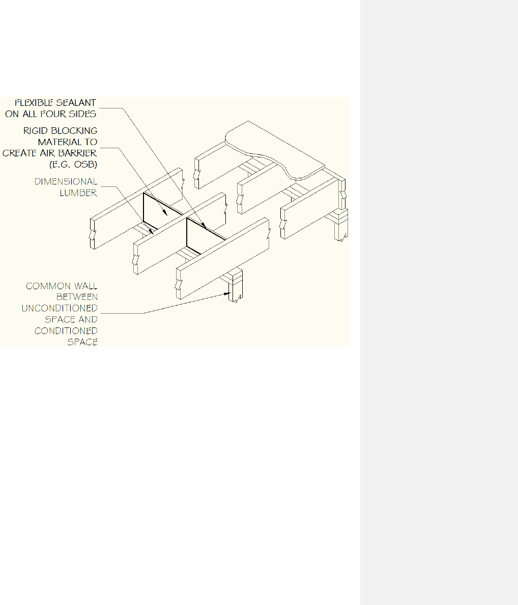
N1102.4.1 Building thermal envelope. The building
thermal envelope shall be durably sealed with an air
barrier system to limit infiltration. The sealing
methods between dissimilar materials shall allow for
differential expansion and contraction. For all homes,
where present, the following shall be caulked,
gasketed, weatherstripped or otherwise sealed with an
air barrier material or solid material consistent with
Appendix E-2.4 of this code:
1. Blocking and sealing floor/ceiling
systems and under knee walls open to
unconditioned or exterior space.
2. Capping and sealing shafts or chases,
including flue shafts.
3. Capping and sealing soffit or dropped
ceiling areas.
N1102.4.2 Air sealing. Building envelope air
tightness shall be demonstrated by Section
N1102.4.2.1 or N1102.4.2.2. Appendix E-3 contains
optional sample worksheets for visual inspection or
testing for the permit holder’s use only.
N1102.4.2.1 Visual inspection option. Building
envelope tightness shall be considered acceptable
when items providing insulation enclosure in
N1102.2.12 and air sealing in N1102.4.1 are
addressed and when the items listed in Table
N1102.4.2, applicable to the method of construction,
are certified by the builder, permit holder or
registered design professional via the certificate in
Appendix E-1.
N1102.4.2.2 Testing option. Building envelope
tightness shall be considered acceptable when items
providing insulation enclosure in N1102.2.12 and air
sealing in N1102.4.1 are addressed and when tested
air leakage is less than or equal to one of the two
following performance measurements:
1. 0.30 CFM50/Square Foot of Surface Area
(SFSA) or
2. Five (5) air changes per hour (ACH50)
when tested with a blower door fan assembly, at a
pressure of 33.5 psf (50 Pa). A single point
depressurization, not temperature corrected, test is
sufficient to comply with this provision, provided
that the blower door fan assembly has been certified
by the manufacturer to be capable of conducting tests
in accordance with ASTM E779-03. Testing shall
occur after rough in and after installation of
penetrations of the building envelope, including
penetrations for utilities, plumbing, electrical,
ventilation and combustion appliances. Testing shall
be reported by the permit holder, a NC licensed
general contractor, a NC licensed HVAC contractor,
a NC licensed Home Inspector, a registered design
professional, a certified BPI Envelope Professional or
a certified HERS rater.
During testing:
1. Exterior windows and doors, fireplace and
stove doors shall be closed, but not sealed;
2. Dampers shall be closed, but not sealed,
including exhaust, backdraft, and flue
dampers;
3. Interior doors shall be open;
4. Exterior openings for continuous ventilation
systems, air intake ducted to the return side
of the conditioning system, and energy or
heat recovery ventilators shall be closed and
sealed;
5. Heating and cooling system(s) shall be
turned off; and
6. Supply and return registers shall not be
sealed.
The air leakage information, including building air
leakage result, tester name, date, and contact
information, shall be included on the certificate
described in Section N1101.9.
For Test Criteria 1 above, the report shall be
produced in the following manner: perform the
blower door test and record the CFM50. Calculate the
total square feet of surface area for the building
thermal envelope (all floors, ceilings, and walls,
including windows and doors, bounding conditioned
space) and record the area. Divide CFM50 by the
total square feet and record the result. If the result is
less than or equal to [0.30 CFM50/SFSA] the
envelope tightness is acceptable; or
For Test Criteria 2 above, the report shall be
produced in the following manner: Perform a blower
door test and record the CFM50. Multiply the
CFM50 by 60 minutes to create CFHour50 and
record. Then calculate the total conditioned volume
of the home and record. Divide the CFH50 by the
total volume and record the result. If the result is less
than or equal to [5 ACH50] the envelope tightness is
acceptable
TABLE N1102.4.2
AIR BARRIER INSPECTION
COMPONENT
CRITERIA
Ceiling/attic
Sealants or gaskets provide a continuous air barrier system joining the top plate of
framed walls with either the ceiling drywall or the top edge of wall drywall to prevent
air leakage.
Top plate penetrations are sealed.
For ceiling finishes that are not air barrier systems such as tongue-and-groove planks,
air barrier systems,(for example, taped house wrap), shall be used above the finish
Note: It is acceptable that sealants or gaskets applied as part of the application of the
drywall will not be observable by the code official.
Walls
Sill plate is gasketed or sealed to subfloor or slab.
Windows and doors
Space between window and exterior door jambs and framing is sealed.
Floors (including above-garage
and cantilevered floors)
Air barrier system is installed at any exposed edge of insulation.
Penetrations
Utility penetrations through the building thermal envelope, including those for
plumbing, electrical wiring, ductwork, security and fire alarm wiring, and control
wiring, shall be sealed.
Garage separation
Air sealing is provided between the garage and conditioned spaces. An air barrier
system shall be installed between the ceiling system above the garage and the ceiling
system of interior spaces.
Duct boots
Sealing HVAC register boots and return boxes to subfloor or drywall.
Recessed lighting
Recessed light fixtures are air tight, IC rated, and sealed to drywall.
Exception—fixtures not penetrating the building envelope.
N1102.4.3 Fireplaces. Site-built masonry solid fuel-
burning fireplaces shall have doors and comply with
Section \R1006 of the North Carolina Residential
Code for combustion air.
N1102.4.4 Fenestration air leakage. Windows,
skylights and sliding glass doors shall have an air
infiltration rate of no more than 0.3 cfm per square
foot (1.5 L/s/m2), and swinging doors no more than
0.5 cfm per square foot (2.6 L/s/m2), when tested
according to NFRC 400 or AAMA/WDMA/CSA
101/I.S.2/A440 by an accredited, independent
laboratory and listed and labeled by the
manufacturer.
Exception: Site-built windows, skylights
and doors.
N1102.4.5 Recessed lighting. Recessed luminaires
installed in the building thermal envelope shall be
sealed to limit air leakage between conditioned and
unconditioned spaces. All recessed luminaires shall
be IC-rated and labeled as meeting ASTM E 283
when tested at 1.57 psf (75 Pa) pressure differential
with no more than 2.0 cfm (0.944 L/s) of air
movement from the conditioned space to the ceiling
cavity. All recessed luminaires shall be sealed with a
gasket or caulk between the housing and the interior
wall or ceiling covering.
N1102.5 Maximum fenestration U-factor and
SHGC
The area-weighted average maximum fenestration U-
factor permitted using trade-offs from Section
1102.1.4 shall be 0.40. Maximum skylight U-factors
shall be 0.65 in zones 4 and 5 and 0.60 in zone 3.

SECTION N1103
SYSTEMS
N1103.1 Controls. At least one thermostat shall be
provided for each separate heating and cooling
system.
N1103.1.1 Programmable thermostat. Where the
primary heating system is a forced-air furnace, at
least one thermostat per dwelling unit shall be
capable of controlling the heating and cooling system
on a daily schedule to maintain different temperature
set points at different times of the day. This
thermostat shall include the capability to set back or
temporarily operate the system to maintain zone
temperatures down to 55°F (13°C) or up to 85°F
(29°C).
N1103.1.2 Heat pump supplementary heat. Heat
pumps having supplementary electric-resistance heat
shall have controls that, except during defrost,
prevent supplemental heat operation when the heat
pump compressor can meet the heating load.
A heat strip outdoor temperature lockout shall be
provided to prevent supplemental heat operation in
response to the thermostat being changed to a warmer
setting. The lockout shall be set no lower than 35 F
and no higher than 40
o
F.
1103.1.3 Maintenance information. Maintenance
instructions shall be furnished for equipment and
systems that require preventive maintenance.
Required regular maintenance actions shall be
clearly stated and incorporated on a readily
accessible label. The label shall include the title or
publication number for the operation and
maintenance manual for that particular model
and type of product.
N1103.2 Ducts.
N1103.2.1 Insulation. Supply and return ducts in
unconditioned space and outdoors shall be in
insulated to R-8. Supply ducts inside
semiconditioned space shall be insulated to R-4;
return ducts inside conditioned and semi-conditioned
space are not required to be insulated. Ducts located
inside conditioned space are not required to be
insulated other than as may be necessary for
preventing the formation of condensation on the
exterior of cooling ducts.
N1103.2.2 Sealing All ducts, air handlers, filter
boxes and building cavities used as ducts shall be
sealed. Joints and seams shall comply with Part V –
Mechanical, Section 603.9 of the North Carolina
Residential Code.
Duct tightness shall be verified as follows:
Total duct leakage less than or equal to 6 CFM (18
L/min) per 100 ft2 (9.29 m2) of conditioned floor area
served by that system when tested at a pressure
differential of 0.1 inches w.g. (25 Pa) across the
entire system, including the manufacturer’s air
handler enclosure.
During testing:
1. Block, if present, the ventilation air duct
connected to the conditioning system.
2. The duct air leakage testing equipment
shall be attached to the largest return in the
system or to the air handler.
3. The filter shall be removed and the air
handler power shall be turned off.
4.Supply boots or registers and return boxes
or grilles shall be taped, plugged, or
otherwise sealed air tight.
5.The hose for measuring the 25 Pascals of
pressure differential shall be inserted into
the boot of the supply that is nominally
closest to the air handler.
6. Specific instructions from the duct testing
equipment manufacturer shall be followed to
reach duct test pressure and measure duct air
leakage.
Testing shall be performed and reported by the
permit holder, a NC licensed general contractor, a
NC licensed HVAC contractor, a NC licensed Home
Inspector, a registered design professional, a certified
BPI Envelope Professional or a certified HERS rater.
A single point depressurization, not temperature
corrected, test is sufficient to comply with this
provision, provided that the duct testing fan assembly
has been certified by the manufacturer to be capable
of conducting tests in accordance with ASTM E1554-
07.
The duct leakage information, including duct leakage
result, tester name, date, and contact information,
shall be included on the certificate described in
Section N1101.9.
For the Test Criteria, the report shall be produced in
the following manner: perform the HVAC system air
leakage test and record the CFM25. Calculate the
total square feet of Conditioned Floor Area (CFA)
served by that system. Multiply the CFM25 by 100,
then divide by the Conditioned Floor Area to find the
CFM25/100SF and record the result. If the result is

less than or equal to [6CFM25/100 SF] the HVAC
system air tightness is acceptable. Appendix E-3C
contains optional sample worksheets for duct testing
for the permit holder’s use only.
Exceptions to testing requirements:
1. Duct systems or portions thereof inside
the building thermal envelope shall not be
required to be leak tested.
2. Installation of a partial system as part of
replacement, renovation or addition does not
require a duct leakage test.
N1103.2.3 Building cavities. Building framing
cavities shall not be used as supply ducts.
N1103.3 Mechanical system piping insulation.
Mechanical system piping capable of carrying fluids
above 105°F (41°C) or below55°F (13°C) shall be
insulated to a minimum of R-3.
N1103.4 Circulating hot water systems. All
circulating service hot water piping shall be insulated
to at least R-2. Circulating hot water systems shall
include an automatic or readily accessible manual
switch that can turn off the hot water circulating
pump when the system is not in use.
N1103.5 Mechanical ventilation. Exhausts shall
have automatic or gravity dampers that close when
the ventilation system is not operating.
N1103.6 Equipment sizing and efficiency.
N1103.6.1 Equipment Sizing. Heating and cooling
equipment shall be sized in accordance with the
mechanical section of the North Carolina Residential
Code.
N1103.6.2 Equipment Efficiencies. Equipment
efficiencies shall comply with the current NAECA
minimum standards.
N1103.7 Snow melt system controls. Snow- and ice-
melting systems, supplied through energy service to
the building, shall include automatic controls capable
of shutting off the system when the pavement
temperature is above 50°F, and no precipitation is
falling and an automatic or manual control that will
allow shutoff when the outdoor temperature is above
40°F.
N1103.8 Pools, inground permanently installed
spas (Mandatory). Pools and inground
permanently installed spas shall be provided with
energy-conserving measures in accordance with
Sections N1103.8.1 through N1103.8.3.
N1103.8.1 Pool Heaters. All heaters shall be
equipped with a readily accessible on-off switch that
is mounted outside of the heater to allow shutting
off the heater without adjusting the thermostat
setting. Gas-fired heaters shall not be equipped
with constant burning pilot lights.
N1103.8.2 Time switches. Time switches or other
control methods that can automatically turn off and
on heaters and pumps according to a preset schedule
shall be installed on all swimming pool heaters and
pumps. Heaters, pumps and motors that have
built-in timers shall be deemed in compliance with
this requirement.
Exceptions:
1. Where public health standards require 24-
hour pump operation.
2. Where pumps are required to operate
solar- and waste-heat-recovery pool heating
systems.
N1103.8.3 Pool covers. Heated pools and inground
permanently installed spas shall be equipped
provided with a vapor-retardant pool cover on or at
the water surface. Pools heated to more than 90°F
(32°C) shall have a pool cover with a minimum
insulation value of R-12.
Exception: Pools deriving over 70 60
percent of the energy for heating from site-
recovered energy, such as a heat pump or
solar energy source computed over an
operating season.
SECTION N1104
LIGHTING SYSTEMS
N1104.1 Lighting equipment. A minimum of 75
percent of the lamps in permanently installed lighting
fixtures shall be high-efficacy lamps.
APPENDIX E-1: RESIDENTIAL REQUIREMENTS
Energy Efficiency Certificate (Section N1101.9)
ENERGY EFFICIENCY CERTIFICATE
N1101.9
Builder, Permit Holder or Registered Design Professional Print
Name:
Signature:
Property Address:
Date:
Insulation Rating - List the value covering largest
area to all that apply
R-Value
Ceiling/roof:
R-
Wall:
R-
Floor:
R-
Closed Crawl Space Wall:
R-
Closed Crawl Space Floor:
R-
Slab:
R-
Basement Wall:
R-
Fenestration:
U-Factor
Solar Heat Gain Coefficient(SHGC)
Building Air Leakage
Visually inspected according to N1102.4.2.1 OR
Building Air Leakage Test Results (Sec.
N1102.4.2.2)
ACH50 [Target: 5.0]
or CFM50/SFSA [Target: 0.30]
Name of Tester / Company:
Date: Phone:
Ducts:
Insulation
R-
Total Duct Leakage Test Result (Sect. N1103.2.2)
(CFM25 Total/100SF) [Target: 6]
Name of Tester or Company:
Date: Phone:
Certificate to be displayed permanently
APPENDIX E-2
INSULATION AND AIR SEALING DETAILS
APPENDIX E-2.1
N1102.2.1 Ceilings with attic spaces: Exception for fully enclosed attic floor systems
SECTION VIEW OF CEILING WITH ATTIC SPACE
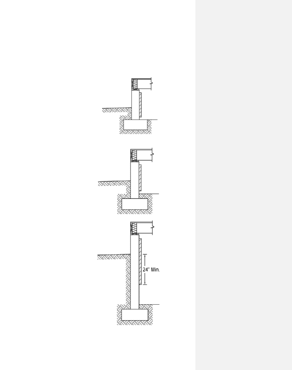
APPENDIX E-2.2
N1102.2.9 Closed crawl space walls. Insulation illustrations
Foam or porous insulation has
3” top inspection gap and
extends down 24” below grade
Foam or porous insulation has
3” top inspection gap and
extends down 3” above
interior ground surface
Foam or porous insulation has
3” top inspection gap and
extends down 3” above top of
wall footing or concrete floor
APPENDIX E-2.3
N1102.2.12 Framed cavity walls. Insulation enclosure – 1. Tubs
SECTION VIEW OF BATH TUB ON EXTERIOR WALL
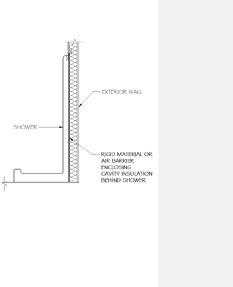
N1102.2.12 Framed cavity walls. Insulation enclosure – 2. Showers
SECTION VIEW OF SHOWER ON EXTERIOR WALL
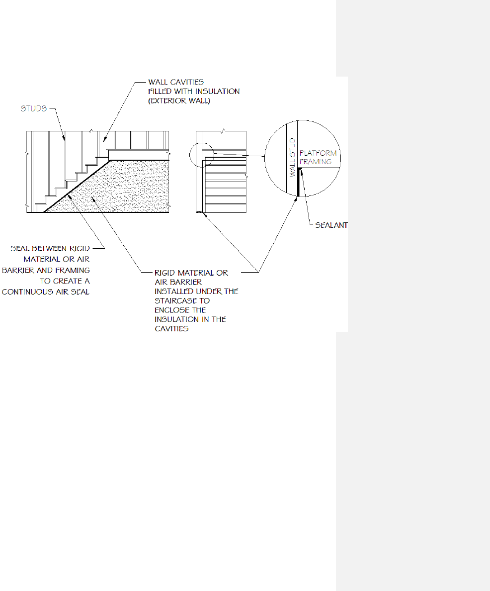
N1102.2.12 Framed cavity walls. Insulation enclosure – 3. Stairs
SECTION VIEW OF INTERIOR STAIRCASE ON EXTERIOR WALL
(OPTION 1)
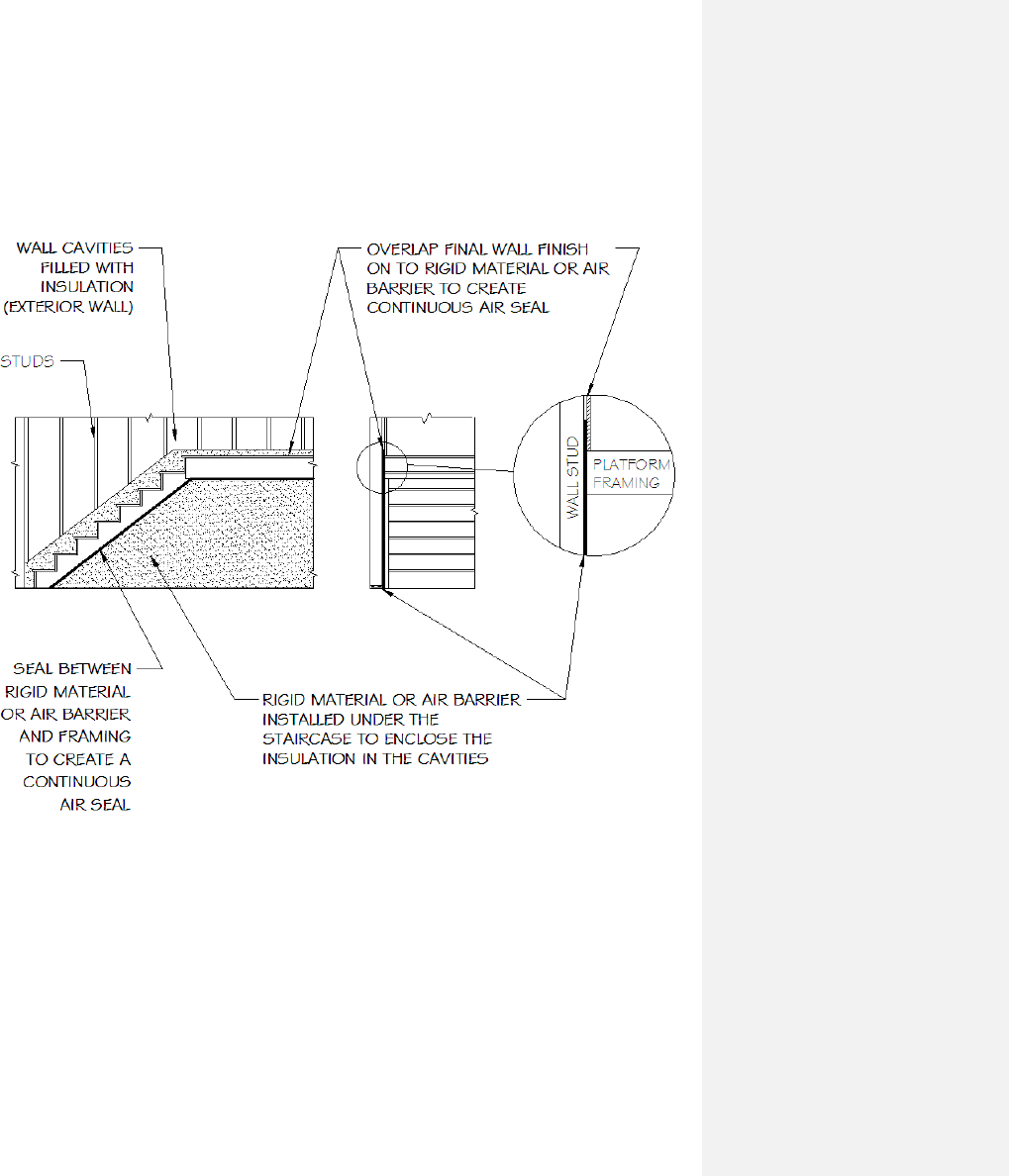
N1102.2.12 Framed cavity walls. Insulation enclosure – 3. Stairs
SECTION VIEW OF INTERIOR STAIRCASE ON EXTERIOR WALL
(OPTION 2)

N1102.2.12 Framed cavity wall. Insulation enclosure – 4. Direct vent gas fireplace
SECTION VIEW OF DIRECT VENT GAS FIREPLACE
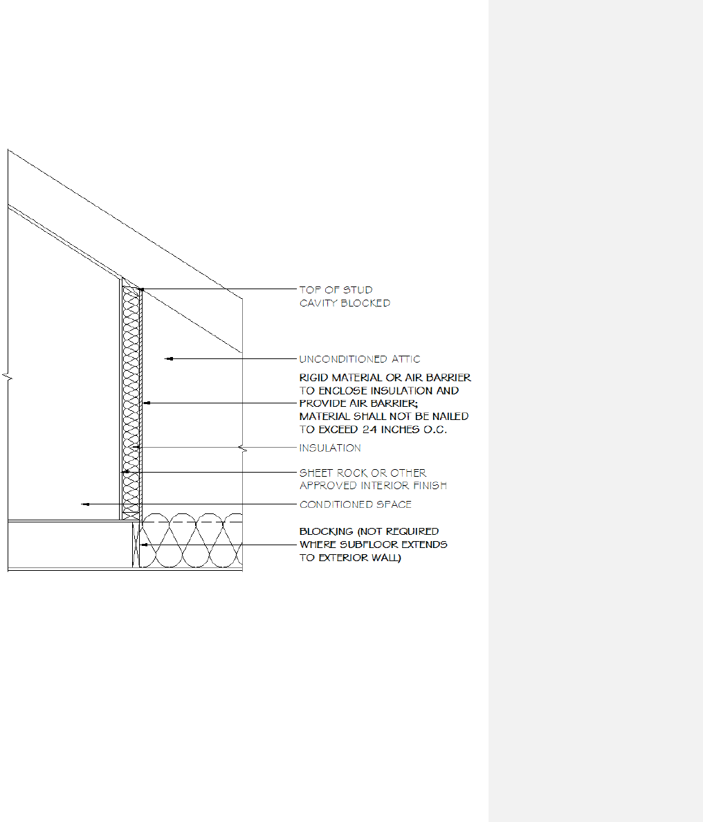
N1102.2.12 Framed cavity walls. Insulation enclosure – 5. Walls that adjoin attic spaces
SECTION VIEW OF WALL ADJOINING ATTIC SPACE
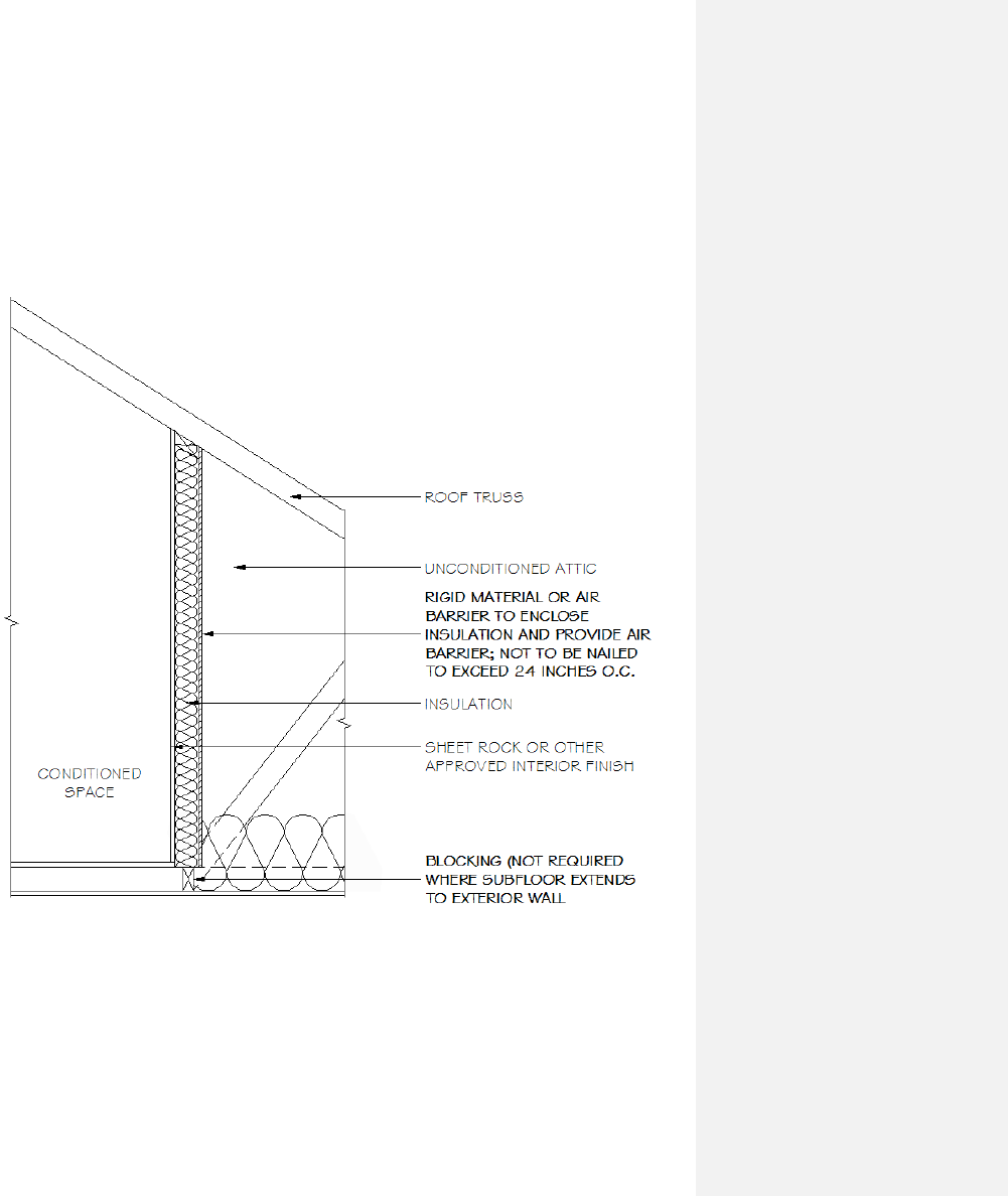
N1102.2.12 Framed cavity walls. Insulation enclosure – 5. Walls that adjoin attic spaces
SECTION VIEW OF WALL ADJOINING ATTIC SPACE
APPENDIX E-2.4
N1102.4.1 Building thermal envelope. – 1. Block and seal floor/ceiling systems
ISOMETRIC VIEW OF DIMENSIONAL LUMBER FLOOR/CEILING SYSTEM
ABOVE COMMON WALL BETWEEN UNCONDITIONED AND CONDITIONED
SPACE
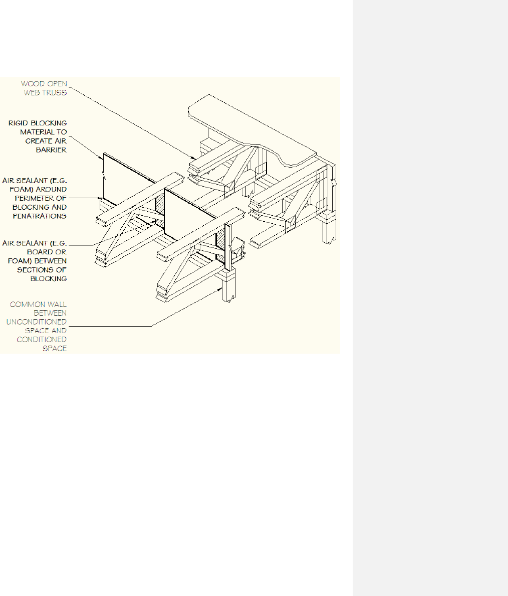
N1102.4.1 Building thermal envelope. – 1. Block and seal floor/ceiling systems
ISOMETRIC VIEW OF WOOD TRUSS FLOOR/CEILING SYSTEM ABOVE
COMMON WALL BETWEEN UNCONDITIONED AND CONDITIONED SPACE
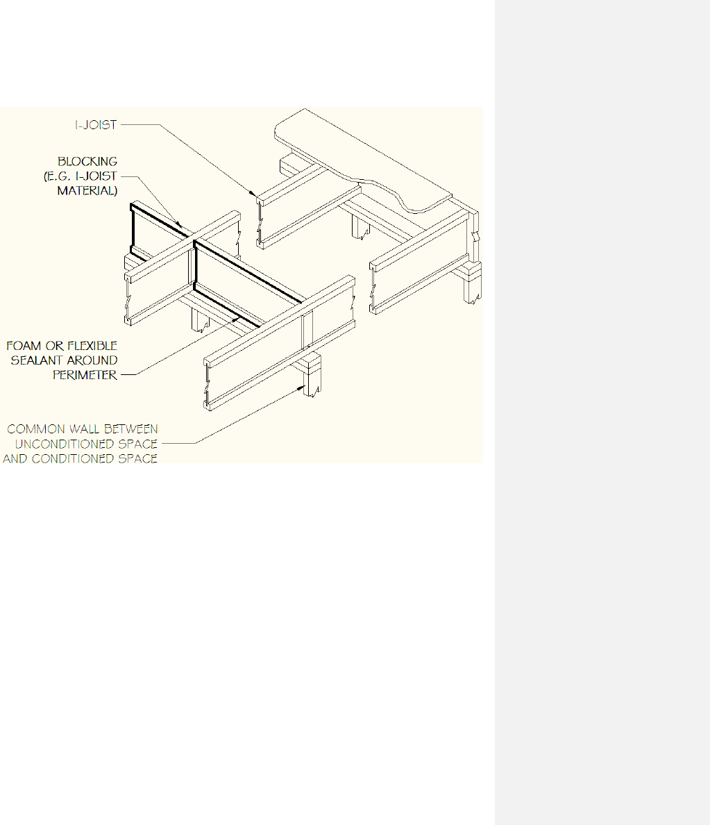
N1102.4.1 Building thermal envelope. – 1. Block and seal floor/ceiling systems
ISOMETRIC VIEW OF I-JOIST FLOOR/CEILING SYSTEM ABOVE COMMON
WALL BETWEEN UNCONDITIONED AND CONDITIONED SPACE
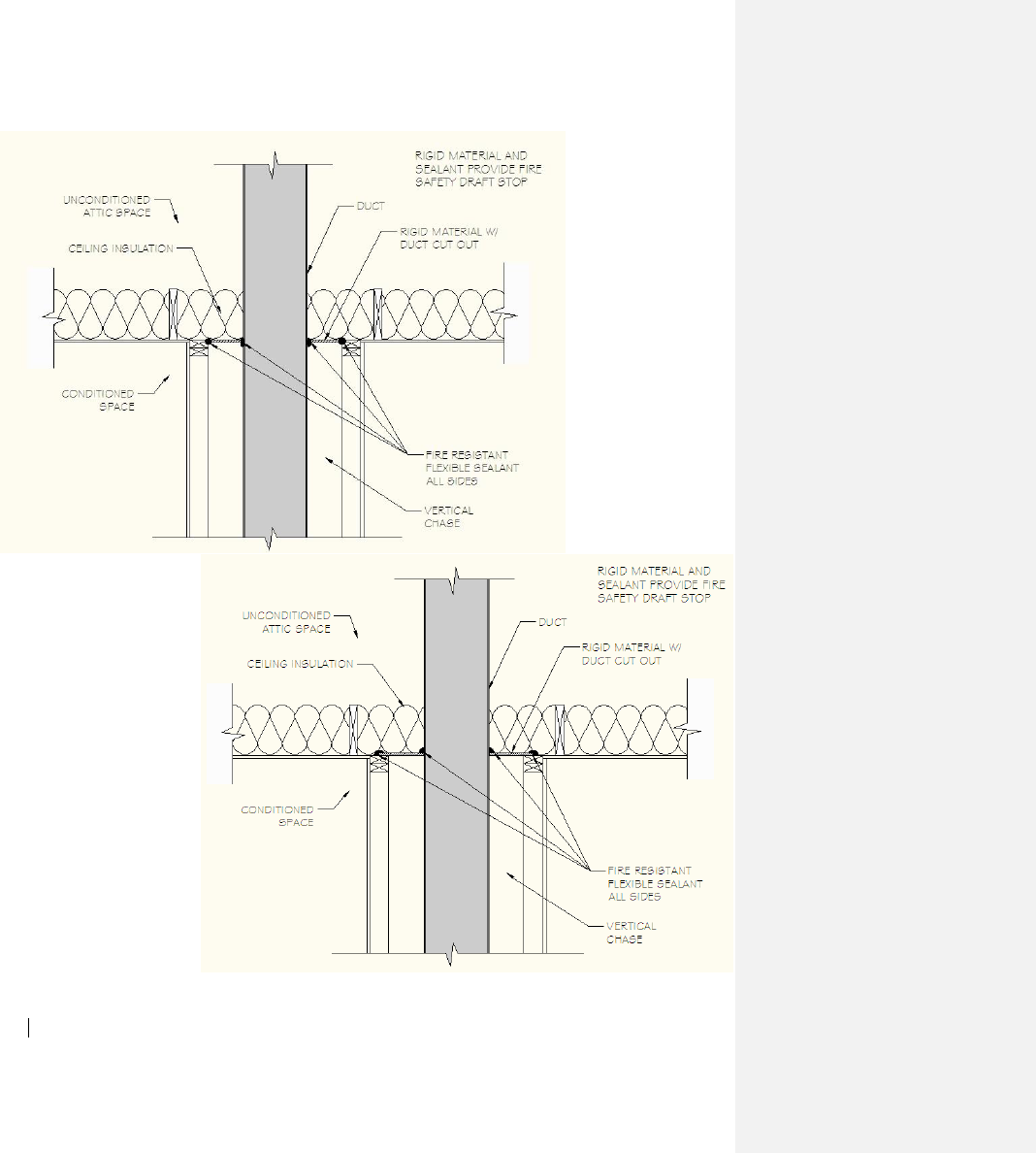
N1102.4.1 Building thermal envelope – 2. Cap and seal shafts and chases
SECTION VIEWS OF DUCT PENETRATING INTO ATTIC
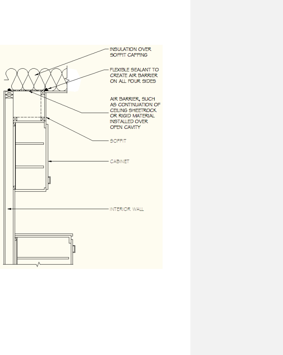
N1102.4.1 Building thermal envelope. – 3. Cap and seal soffit or dropped ceiling
SECTION VIEW OF SOFFIT OVER CABINET
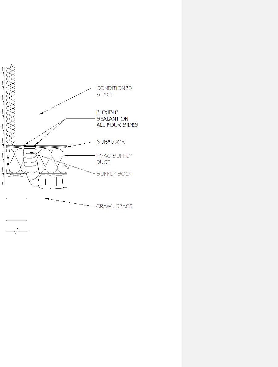
N1102.4.1 Building thermal envelope. – 4. Seal HVAC boot penetration – floor
SECTION VIEW OF FLOOR HVAC BOOT PENETRATION
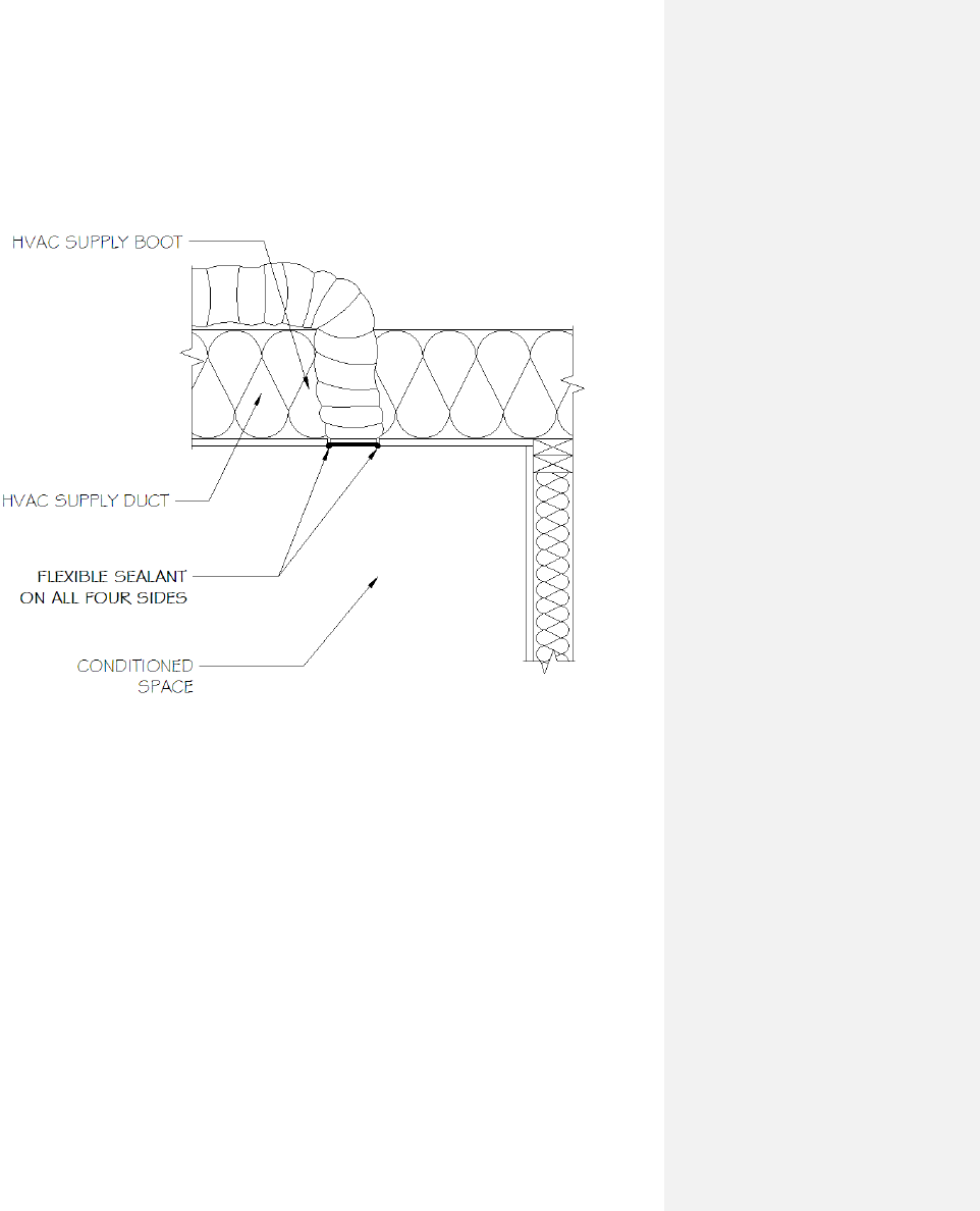
N1102.4.1 Building thermal envelope. – 4. Seal HVAC boot penetration – ceiling
SECTION VIEW OF CEILING HVAC BOOT PENETRATION
APPENDIX E-3:
SAMPLE WORKSHEETS FOR RESIDENTIAL AIR AND DUCT LEAKAGE TESTING
APPENDIX E-3A: Air sealing: Visual inspection option (Section N1102.4.2.1)
Sample Worksheet
N1102.4.2 Air sealing. Building envelope air tightness shall be demonstrated by Section N1102.4.2.1 or
N1102.4.2.2:
N1102.4.2.1 Visual inspection option. Building envelope tightness shall be considered acceptable when items
providing insulation enclosure in N1102.2.12 and air sealing in N1102.4.1 are addressed and when the items listed
in Table N1102.4.2, applicable to the method of construction, are certified by the by the builder, permit holder or
registered design professional via the certificate in Appendix E-1.
TABLE N1102.4.2
AIR BARRIER INSPECTION
COMPONENT
CRITERIA
Ceiling/attic
Sealants or gaskets provide a continuous air barrier system joining the top plate of
framed walls with either the ceiling drywall or the top edge of wall drywall to prevent
air leakage.
Top plate penetrations are sealed.
For ceiling finishes that are not air barrier systems such as tongue-and-groove planks,
air barrier systems,(for example, taped house wrap), shall be used above the finish
Note: It is acceptable that sealants or gaskets applied as part of the application of the
drywall will not be observable by the code official.
Walls
Sill plate is gasketed or sealed to subfloor or slab.
Windows and doors
Space between window and exterior door jambs and framing is sealed.
Floors (including above-garage
and cantilevered floors)
Air barrier system is installed at any exposed edge of insulation.
Penetrations
Utility penetrations through the building thermal envelope, including those for
plumbing, electrical wiring, ductwork, security and fire alarm wiring, and control
wiring, shall be sealed.
Garage separation
Air sealing is provided between the garage and conditioned spaces. An air barrier
system shall be installed between the ceiling system above the garage and the ceiling
system of interior spaces.
Duct boots
Sealing HVAC register boots and return boxes to subfloor or drywall.
Recessed lighting
Recessed light fixtures are air tight, IC rated, and sealed to drywall.
Exception—fixtures not penetrating the building envelope.
Property Address:
______________________________________________________________________________
N1102.4.2.1 Visual Inspection Option
The inspection information including tester name, date, and contact shall be included on the certificate
described in Section N1101.9.
________________________________________________ ______________________________
Signature Date

APPENDIX E-3B
Air sealing: Testing option (Section N1102.4.2.2)
Sample Worksheet
N1102.4.2 Air sealing. Building envelope air tightness shall be demonstrated by Section N1102.4.2.1 or
N1102.4.2.2:
N1102.4.2.2 Testing option. Building envelope tightness shall be considered acceptable when items providing
insulation enclosure in N1102.2.12 and air sealing in N1102.4.1 are addressed and when tested air leakage is less
than or equal to one of the two following performance measurements:
1. 0.304 CFM50/Square Foot of Surface Area (SFSA) or
2. Five (5) air changes per hour (ACH50)
When tested with a blower door fan assembly, at a pressure of 33.5 psf (50 Pa). A single point depressurization, not
temperature corrected, test is sufficient to comply with this provision, provided that the blower door fan assembly
has been certified by the manufacturer to be capable of conducting tests in accordance with ASTM E779-03.
Testing shall occur after rough in and after installation of penetrations of the building envelope, including
penetrations for utilities, plumbing, electrical, ventilation and combustion appliances. Testing shall be reported by
the permit holder, a NC licensed general contractor, a NC licensed HVAC contractor, a NC licensed Home
Inspector, a registered design professional, a certified BPI Envelope Professional or a certified HERS rater.
During testing:
1. Exterior windows and doors, fireplace and stove doors shall be closed, but not sealed;
2. Dampers shall be closed, but not sealed, including exhaust, backdraft, and flue dampers;
3. Interior doors shall be open;
4. Exterior openings for continuous ventilation systems, air intake ducted to the return side of the conditioning
system, and energy or heat recovery ventilators shall be closed and sealed;
5. Heating and cooling system(s) shall be turned off; and
6. Supply and return registers shall not be sealed.
The air leakage information, including building air leakage result, tester name, date, and contact information, shall
be included on the certificate described in Section N1101.9.
For Test Criteria 1 above, the report shall be produced in the following manner: Perform the blower door test and
record the CFM50___________. Calculate the total square feet of surface area for the building thermal envelope, all
floors, ceilings, and walls (this includes windows and doors) and record the area______________. Divide CFM50
by the total square feet and record the result below. If the result is less than or equal to [0.30 CFM50/SFSA] the
envelope tightness is acceptable; or
For Test Criteria 2 above, the report shall be produced in the following manner: Perform a blower door test and
record the CFM50___________. Multiply the CFM50 by 60 minutes to create CFHour50 and record
______________. Then calculate the total conditioned volume of the home and record_________________. Divide
the CFH50 by the total volume and record the result below. If the result is less than or equal to [5 ACH50] the
envelope tightness is acceptable.
Property Address:
______________________________________________________________________________
Company Name ________________________________________________________________
Contact Information : ____________________________________________________________
_______________________________________________________________________________
____________________________________________ _______________
Signature of Tester Date
Permit Holder, NC Licensed General Contractor, NC Licensed HVAC Contractor,
NC Licensed Home Inspector, Registered Design Professional,
Certified BPI Envelope Professional, or Certified HERS Rater (circle one)

APPENDIX E-3C
Duct sealing. Duct air leakage test (Section N1103.2.2)
Sample Worksheet
N1103.2.2 Sealing All ducts, air handlers, filter boxes and building cavities used as ducts shall be sealed. Joints and
seams shall comply with Part V – Mechanical, Section 603.9 of the North Carolina Residential Code.
Duct tightness shall be verified as follows:
Total duct leakage less than or equal to 6 CFM (18 L/min) per 100 ft
2
(9.29 m2) of conditioned floor area served by
that system when tested at a pressure differential of 0.1 inches w.g. (25 Pa) across the entire system, including the
manufacturer’s air handler enclosure.
During testing:
1. Block, if present, the ventilation air duct connected to the conditioning system.
2. The duct air leakage testing equipment shall be attached to the largest return in the system or to the air
handler.
3. The filter shall be removed and the air handler power shall be turned off.
4. Supply boots or registers and return boxes or grilles shall be taped, plugged, or otherwise sealed air tight.
5. The hose for measuring the 25 Pascals of pressure differential shall be inserted into the boot of the
supply that is nominally closest to the air handler.
6. Specific instructions from the duct testing equipment manufacturer shall be followed to reach duct test
pressure and measure duct air leakage.
Testing shall be performed and reported by the permit holder, a NC licensed general contractor, a NC licensed
HVAC contractor, a NC licensed Home Inspector, a registered design professional, a certified BPI Envelope
Professional or a certified HERS rater. A single point depressurization, not temperature corrected, test is sufficient to
comply with this provision, provided that the duct testing fan assembly has been certified by the manufacturer to be
capable of conducting tests in accordance with ASTM E1554-07.
The duct leakage information, including duct leakage result, tester name, date, company and contact information,
shall be included on the certificate described in Section N1101.9.
For the Test Criteria, the report shall be produced in the following manner: perform the HVAC system air leakage
test and record the CFM25. Calculate the total square feet of Conditioned Floor Area (CFA) served by that system.
Multiply CFM25 by 100, divide the result by the CFA and record the result. If the result is less than or equal to [6
CFM25/100 SF] the HVAC system air tightness is acceptable.
Complete one duct leakage report for each HVAC system serving the home:
Property Address: ________________________________________________________________
HVAC System Number: _________ Describe area of home served: _____________________
CFM25 Total _________. Conditioned Floor Area (CFA) served by system: __________ s.f.
CFM25 x 100 divided by CFA = ____ CFM25/100SF (e.g. 100 CFM25x100/ 2,000 CFA = 5 CFM25/100SF)
Fan attachment location ___________________
Company Name __________________________________________________________________
Contact Information:_______________________________________________________________
_______________________________________________________________________________
_______________________________________ ______________________________
Signature of Tester Date
Permit Holder, NC Licensed General Contractor, NC Licensed HVAC Contractor,
NC Licensed Home Inspector, Registered Design Professional,
Certified BPI Envelope Professional, or Certified HERS Rater (circle one)

APPENDIX E-4 ADDITIONAL VOLUNTARY CRITERIA FOR INCREASING ENERGY
EFFICIENCY (High Efficiency Residential Option)
1. Introduction. The increased energy efficiency measures identified in this appendix are strictly voluntary
at the option of the permit holder and have been evaluated to be the most cost effective measures for
achieving an additional 15-20% energy efficiency beyond the code minimums.
2. Requirements: Follow all sections of the Chapter 11 of the North Carolina Residential Energy Code,
except the following.
a. Instead of using Table N1102.1 in Section N1102.1, use Table E-4A shown below.
TABLE E-4A
OPTIONAL INSULATION AND FENESTRATION REQUIREMENTS BY COMPONENTa
CLIMATE
ZONE
FENESTRATION
U-FACTORb
SKYLIGHTb
U-FACTOR
GLAZED
FENESTRATION
SHGCb, e
CEILING
R-VALUEk
WOOD
FRAME WALL
R-VALUE e
MASS
WALL
R-VALUEi
FLOOR
R-VALUE
BASEMENTc
WALL
R-VALUE
SLABd
R-VALUE
CRAWL
SPACEc
WALL
R-VALUE
3
0.32
0.65
0.25
38
19, 13+5,
or 15+3
eh
5/10
19
10/13f
5
10/13
4
0.32
0.60
0.25
38
19, 13+5,
or 15+3
eh
5/10
19
10/13
10
10/13
5
0.32
0.60
(NR)
38
19, 13+5,
or 15+3
eh
13/17
30g
10/13
10
15/19
For SI: 1 foot = 304.8 mm.
a. R-values are minimums. U-factors and SHGC are maximums.
b. The fenestration U-factor column excludes skylights. The SHGC column applies to all glazed fenestration.
c. ―10/13‖ means R-10 continuous insulated sheathing on the interior or exterior of the home or R-13 cavity insulation at the interior of the
basement wall or crawl space wall.
d. For monolithic slabs, insulation shall be applied from the inspection gap downward to the bottom of the footing or a maximum of 18 inches
below grade . For floating slabs, insulation shall extend to the bottom of the foundation wall or 24 inches, whichever is less. (See Appendix O)
R-5 shall be added to the required slab edge R-values for heated slabs.
e. R -19 fiberglass batts compressed and installed in a nominal 2 × 6 framing cavity is deemed to comply. Fiberglass batts rated R-19 or higher
compressed and installed in a 2x4 wall is not deemed to comply.
f. Basement wall insulation is not required in warm-humid locations as defined by Figure N1101.2(1 and 2) and Table N1101.2.
g. Or insulation sufficient to fill the framing cavity, R-19 minimum.
h. ―13+5‖ means R-13 cavity insulation plus R-5 insulated sheathing. 15+3 means R-15 cavity insulation plus R-3 insulated sheathing. If
structural sheathing covers 25 percent or less of the exterior, insulating sheathing is not required where structural sheathing is used. If structural
sheathing covers more than 25 percent of exterior, structural sheathing shall be supplemented with insulated sheathing of at least R-2. 13+2.5
means R-13 cavity insulation plus R-2.5 sheathing.
i. For Mass Walls, the second R-value applies when more than half the insulation is on the interior of the mass wall.
j. R-30 shall be deemed to satisfy the ceiling insulation requirement wherever the full height of uncompressed R-30 insulation extends
over the wall top plate at the eaves. Otherwise R-38 insulation is required where adequate clearance exists or insulation must extend to
either the insulation baffle or within 1” of the attic roof deck.
k. Table value required except for roof edge where the space is limited by the pitch of the roof, there the insulation must fill the space up to the air
baffle.
b. Instead of using Table N1102.2 in Section N1102.2, use Table E-4B to find the maximum U-
factors for building components.
3. TABLE E-4B
4. EQUIVALENT U-FACTORSa
CLIMATE
ZONE
FENESTRATION
U-FACTOR
SKYLIGHT
U-FACTOR
CEILING
U-FACTOR
FRAME
WALL
U-FACTOR
MASS
WALL
U-FACTORb
FLOOR
U-FACTOR
BASEMENT
WALL
U-FACTORd
CRAWL
SPACE
WALL
U-FACTORc
3
0.32
0.65
0.030
0.067
0.141
0.047
0.059
0.065
4
0.32
0.60
0.030
0.067
0.141
0.047
0.059
0.065
5
0.32
0.60
0.030
0.067
0.082
0.033
0.059
0.046
a. Nonfenestration U-factors shall be obtained from measurement, calculation or an approved source.
b. When more than half the insulation is on the interior, the mass wall U-factors shall be a maximum 0.12 in Zone 3, 0.10 in Zone 4, and the same
as the frame wall U-factor in Zone 5.
c. Basement wall U-factor of 0.360 in warm-humid locations as defined by Figures N1101.2(1), N1101.2(2) and Table N1101.2.
d. Foundation U-factor requirements shown in Table E-4B include wall construction and interior air films but exclude soil conductivity and
exterior air films. U-factors for determining code compliance in accordance with Section N1102.1.3 (total UA alternative) shall be modified to
include soil conductivity and exterior air films.
c. Instead of using the air leakage value for maximum leakage shown in Section N1102.4.2.2, use the
following:
i. 0.24 CFM50/Square Foot of Surface Area (SFSA) or
ii. Four (4) air changes per hour (ACH50)
d. Instead of using the duct leakage value for maximum leakage shown in Section N1103.2.2 use the
following:
Total duct leakage less than or equal to 4 CFM (12 L/min) per 100 ft2 (9.29 m2) of
conditioned floor area served by that system when tested at a pressure differential of 0.1
inches w.g. (25 Pa) across
Table E-4C: Sample Confirmation Form for ADDITIONAL VOLUNTARY CRITERIA
FOR INCREASING ENERGY EFFICIENCY (High Efficiency Residential Option)
Insulation and Fenestration Values
Proposed
Project
Values
Climate Zone
3
Fenestration U-Factor
0.32
j
Skylight U-Factor
0.65
Glazed Fenestration SHGC
b, e
0.25
Ceiling R-value
38
Wood Frame Wall R-value
e
19, 13+5,
or 15+3
eh
Mass Wall R-value
j
5/10
Floor R-value 19
Basement Wall R-value
c
10/13
f
Slab R-value and Depth
d
5, 2 ft
Crawl Space Wall R-value
c
10/13
Building Air Leakage
Visually inspected according to
N1102.4.2.1 (check box) OR
Building Air Leakage Test
according to N1102.4.2.2 (check
box). Show test value:
ACH50 [Target: 4.0], or
CFM50/SFSA [Target: 0.24]
Name of Tester / Company:
Date:
Phone:
Duct Insulation and Sealing
Insulation Value
Duct Leakage Test Result
(Sect. N1103.2.2)
(CFM25 Total/100SF)
[Target:4]
Name of Tester or Company:
Date:
Phone:
4
5
0.32
j
0.32
j
0.6
0.6
0.25
(NR)
38
38
19, 13+5, or 15+3
eh
19, 13+5, or 15+3
eh
5/10
13/17
19
30
g
10/13
f
10/13
f
10, 2 ft
10, 2 ft
10/13
15/19
R-
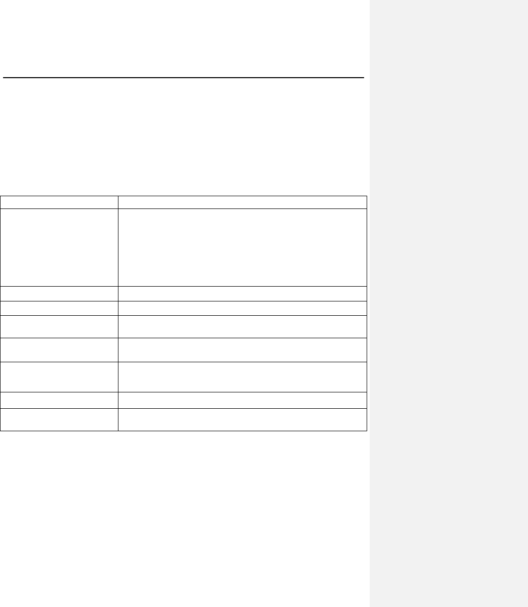
E-4D: SAMPLE WORKSHEETS FOR RESIDENTIAL AIR AND DUCT LEAKAGE
TESTING
E-4D.1
Air sealing: Visual inspection option (Section 402.4.2.1)
Sample Worksheet for Alternative Residential Energy Code for Higher Efficiency
402.4.2 Air sealing. Building envelope air tightness shall be demonstrated by Section 402.4.2.1 or 402.4.2.2:
402.4.2.1 Visual inspection option. Building envelope tightness shall be considered acceptable when items
providing insulation enclosure in 402.2.12 and air sealing in 402.4.1 are addressed and when the items listed in
Table 402.4.2, applicable to the method of construction, are certified by the by the builder, permit holder or
registered design professional via the certificate in Appendix 1.
TABLE 402.4.2
AIR BARRIER INSPECTION
COMPONENT
CRITERIA
Ceiling/attic
Sealants or gaskets provide a continuous air barrier system joining the top plate of
framed walls with either the ceiling drywall or the top edge of wall drywall to prevent
air leakage. Top plate penetrations are sealed.
For ceiling finishes that are not air barrier systems such as tongue-and-groove planks,
air barrier systems,(for example, taped house wrap), shall be used above the finish
Note: It is acceptable that sealants or gaskets applied as part of the application of the
drywall will not be observable by the code official
Walls
Sill plate is gasketed or sealed to subfloor or slab.
Windows and doors
Space between window and exterior door jambs and framing is sealed.
Floors (including above-garage
and cantilevered floors)
Air barrier system is installed at any exposed edge of insulation.
Penetrations
Utility penetrations through the building thermal envelope, including those for
plumbing, electrical wiring, ductwork, security and fire alarm wiring, and control
wiring, shall be sealed.
Garage separation
Air sealing is provided between the garage and conditioned spaces. An air barrier
system shall be installed between the ceiling system above the garage and the ceiling
system of interior spaces.
Duct boots
Sealing HVAC register boots and return boxes to subfloor or drywall.
Recessed lighting
Recessed light fixtures are air tight, IC rated, and sealed to drywall.
Exception—fixtures not penetrating the building envelope.
Property Address:
______________________________________________________________________________
402.4.2.1 Visual Inspection Option
The inspection information including tester name, date, and contact shall be included on the certificate
described in Section 401.3.
________________________________________________ ______________________________
Signature Date

E-4D.2
Air sealing: Testing option (Section 402.4.2.2)
Sample Worksheet for Alternative Residential Energy Code for Higher Efficiency
402.4.2 Air sealing. Building envelope air tightness shall be demonstrated by Section 402.4.2.1 or 402.4.2.2:
402.4.2.2 Testing option. Building envelope tightness shall be considered acceptable when items providing
insulation enclosure in 402.2.12 and air sealing in 402.4.1 are addressed and when tested air leakage is less than or
equal to one of the two following performance measurements:
1. 0.24 CFM50/Square Foot of Surface Area (SFSA) or
2. Four (4) air changes per hour (ACH50)
When tested with a blower door fan assembly, at a pressure of 33.5 psf (50 Pa). A single point depressurization, not
temperature corrected, test is sufficient to comply with this provision, provided that the blower door fan assembly
has been certified by the manufacturer to be capable of conducting tests in accordance with ASTM E779-03.
Testing shall occur after rough in and after installation of penetrations of the building envelope, including
penetrations for utilities, plumbing, electrical, ventilation and combustion appliances. Testing shall be reported by
the permit holder, a NC licensed general contractor, a NC licensed HVAC contractor, a NC licensed Home
Inspector, a registered design professional, a certified BPI Envelope Professional or a certified HERS rater.
During testing:
1. Exterior windows and doors, fireplace and stove doors shall be closed, but not sealed;
2. Dampers shall be closed, but not sealed, including exhaust, backdraft, and flue dampers;
3. Interior doors shall be open;
4. Exterior openings for continuous ventilation systems, air intake ducted to the return side of the conditioning
system, and energy or heat recovery ventilators shall be closed and sealed;
5. Heating and cooling system(s) shall be turned off; and
6. Supply and return registers shall not be sealed.
The air leakage information, including building air leakage result, tester name, date, and contact information, shall
be included on the certificate described in Section 401.3.
For Test Criteria 1 above, the report shall be produced in the following manner: Perform the blower door test and
record the CFM50___________. Calculate the total square feet of surface area for the building thermal envelope, all
floors, ceilings, and walls (this includes windows and doors) and record the area______________. Divide CFM50
by the total square feet and record the result below. If the result is less than or equal to [0.24 CFM50/SFSA] the
envelope tightness is acceptable; or
For Test Criteria 2 above, the report shall be produced in the following manner: Perform a blower door test and
record the CFM50___________. Multiply the CFM50 by 60 minutes to create CFHour50 and record
______________. Then calculate the total conditioned volume of the home and record_________________. Divide
the CFH50 by the total volume and record the result below. If the result is less than or equal to [4 ACH50] the
envelope tightness is acceptable.
Property Address: ____________________________________________________________
______________________________________________________________________________
Company Name ________________________________________________________________
Contact Information : ____________________________________________________________
_______________________________________________________________________________
____________________________________________ _______________
Signature of Tester Date
Permit Holder, NC Licensed General Contractor, NC Licensed HVAC Contractor,
NC Licensed Home Inspector, Registered Design Professional,
Certified BPI Envelope Professional, or Certified HERS Rater (circle one)

E-4D.3
Duct sealing. Duct air leakage test (Section 403.2.2)
Sample Worksheet for Alternative Residential Energy Code for Higher Efficiency
403.2.2 Sealing All ducts, air handlers, filter boxes and building cavities used as ducts shall be sealed. Joints and
seams shall comply with Part V – Mechanical, Section 603.9 of the North Carolina Residential Code.
Duct tightness shall be verified as follows:
Total duct leakage less than or equal to 4 CFM (12 L/min) per 100 ft2 (9.29 m2) of conditioned floor area served by
that system when tested at a pressure differential of 0.1 inches w.g. (25 Pa) across the entire system, including the
manufacturer’s air handler enclosure.
During testing:
1. Block, if present, the ventilation air duct connected to the conditioning system.
2. The duct air leakage testing equipment shall be attached to the largest return in the system or to the air
handler.
3. The filter shall be removed and the air handler power shall be turned off.
3. Supply boots or registers and return boxes or grilles shall be taped, plugged, or otherwise sealed air tight.
4. The hose for measuring the 25 Pascals of pressure differential shall be inserted into the boot of the
supply that is nominally closest to the air handler.
5. Specific instructions from the duct testing equipment manufacturer shall be followed to reach duct test
pressure and measure duct air leakage.
Testing shall be performed and reported by the permit holder, a NC licensed general contractor, a NC licensed
HVAC contractor, a NC licensed Home Inspector, a registered design professional, a certified BPI Envelope
Professional or a certified HERS rater. A single point depressurization, not temperature corrected, test is sufficient to
comply with this provision, provided that the duct testing fan assembly has been certified by the manufacturer to be
capable of conducting tests in accordance with ASTM E1554-07.
The duct leakage information, including duct leakage result, tester name, date, company and contact information,
shall be included on the certificate described in Section 401.3.
For the Test Criteria, the report shall be produced in the following manner: perform the HVAC system air leakage
test and record the CFM25. Calculate the total square feet of Conditioned Floor Area (CFA) served by that system.
Multiply CFM25 by 100, divide the result by the CFA and record the result. If the result is less than or equal to [4
CFM25/100 SF] the HVAC system air tightness is acceptable.
Complete one duct leakage report for each HVAC system serving the home:
Property Address: ________________________________________________________________
HVAC System Number: _________ Describe area of home served: _____________________
CFM25 Total _________. Conditioned Floor Area (CFA) served by system: __________ s.f.
CFM25 x 100 divided by CFA = ____ CFM25/100SF (e.g. 70 CFM25x100/ 2,000 CFA = 3.5 CFM25/100SF)
Fan attachment location ___________________
Company Name __________________________________________________________________
Contact Information:_______________________________________________________________
_______________________________________________________________________________
_______________________________________ ______________________________
Signature of Tester Date
Permit Holder, NC Licensed General Contractor, NC Licensed HVAC Contractor,
NC Licensed Home Inspector, Registered Design Professional,
Certified BPI Envelope Professional, or Certified HERS Rater (circle one)
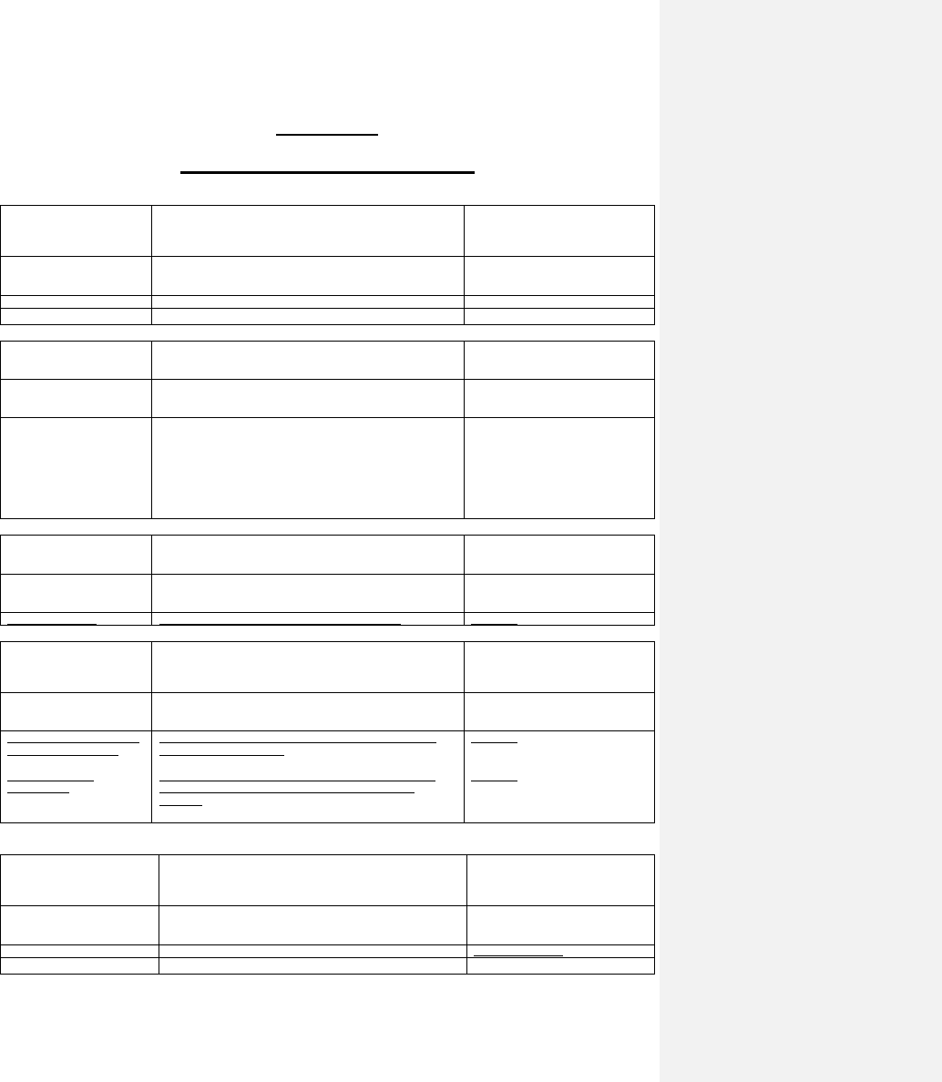
PART IX REFERENCED STANDARDS
CHAPTER 43
REFERENCED STANDARDS
ASHRAE
American Society of Heating, Refrigerating and Air-Conditioning
Engineers, Inc.
1791 Tullie Circle, NE
Atlanta, GA 30329-2305
Standard
reference
number
Title
Referenced
in code
section number
ASHRAE—2005
ASHRAE Handbook of Fundamentals
N1102.1.3
ASTM
ASTM International
100 Barr Harbor Drive
West Conshohocken, PA 19428-2859
Standard
reference
number
Title
Referenced
in code
section number
E 283—04
E779-03
E2178-03
E1554-07
Test Method for Determining the Rate of Air Leakage Through
Exterior Windows, Curtain Walls and Doors Under Specified
Pressure Differences Across the Specimen
Standard Test Method for Determining Air Leakage Rate by Fan
Pressurization
Standard Test Method for Air Permeance of Building Materials
Standard Test Methods for Determining Air Leakage of Air
Distribution Systems by Fan Pressurization
N1102.4.5
N1102.4.2.2
R202
N1103.2.2
CSA
Canadian Standards Association
5060 Spectrum Way
Mississauga, Ontario, Canada L4W 5N6
Standard
reference
number
Title
Referenced
in code
section number
101/I.S.2/A440—08
Specifications for Windows, Doors and Unit Skylights.
N1102.4.4
DOE
U.S. Department of Energy
c/o Superintendent of Documents
U.S. Government Printing Office
Washington, DC 20402-9325
Standard
reference
number
Title
Referenced
in code
section number
NAECA - National Appliance
Energy Conservation Act
Title 10, Volume 3;
10CFR430.32
Minimum energy efficiency standards for residential central air
conditioners and heat pumps
ENERGY CONSERVATION PROGRAM FOR CONSUMER
PRODUCTS, Subpart C: Energy and Water Conservation
Standards
N1103.6.2
N1103.6.2
ICC
International Code Council, Inc.
500 New Jersey Avenue, NW
6th Floor
Washington, DC 20001
Standard
reference
number
Title
Referenced
in code
section number
IRC—09
International Residential Code®
N1102.2.3, N1103.6
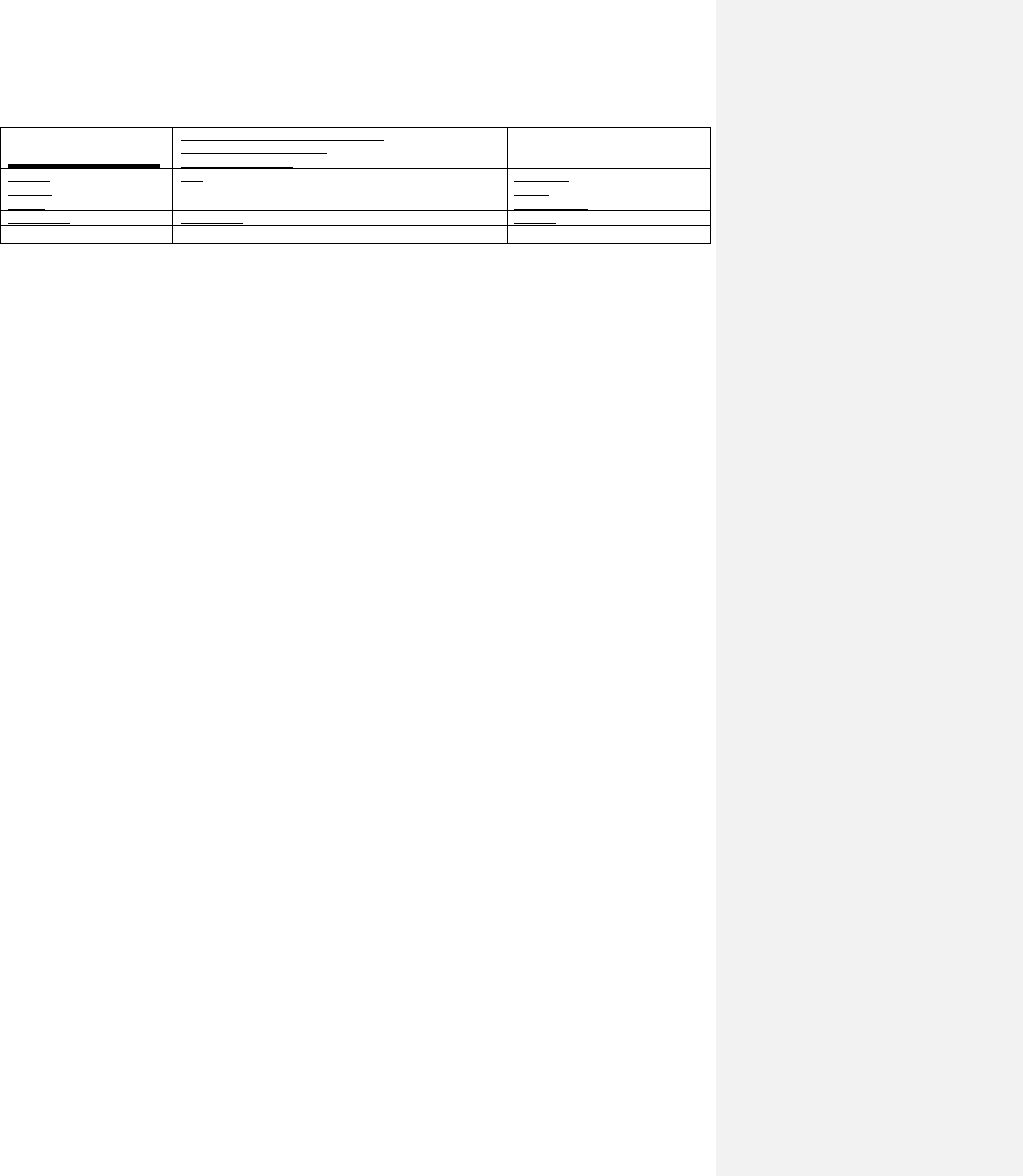
US—FTC
United States - Federal Trade Commission
600 Pennsylvania Avenue NW
Washington, DC 20580
Standard
reference
number
Title
Referenced
in code
section number
CFR Title 16
R-value Rule
N1101.6
