Prepared by MERCHANT MARINE TECHNICAL DIVISION
U. S. Coast Guard
Washington D. C.
1968
United States NVIC 7-68
Coast Guard 28 OCT 1968
NAVIGATION AND VESSEL INSPECTION CIRCULAR NO. 7-68
Electronic Version for Distribution on the World Wide Web
Subj: Notes on Inspection and Repair of Steel Hulls
1. PURPOSE. The attached “Notes on Inspection and Repair of Steel hulls” is intended to
disseminate to Coast Guard Marine Inspectors, Vessel Owners, and Shipyards general
information relating to good practice in the inspection and repair of steel hulled vessels.
This information is furnished for guidance purposes. Where specifics are given it should
be understood that mandatory application is not necessarily intended. Nothing herein
shall be taken as amending applicable regulations, or as a prescribing or limiting the
authority and responsibility of the Officer in Charge, Marine Inspection in the exercise of
his good judgement.
2. DISCUSSION. These notes were first issued in 1960 to fulfill a need for guidance
material on the inspection and repair of steel merchant vessels. Experience in their use
since that time has suggested certain changes which have been included in this revision.
It is believed that these notes cover the more important aspects of hull structural
inspection and repair. However, constructive comments and suggestions are solicited and
will be the basis for such future revision of these notes as may be necessary.
3. CANCELLATION. Navigation and Vessel Inspection Circulars Nos. 7-62 and 4-60 are
hereby cancelled.
4. EFFECTIVE DATE. Upon Receipt.
Encl: (1) Notes on Inspection and Repair of Steel Hulls

- 1 -
CONTENTS
I. PURPOSE
II. GENERAL
III. NOTES ON INSPECTION
(A) DETERIORATION:
(B) GAGING:
(C) CORROSION LIMITS - GENERAL
(D) OVERSIZE OR UNDERSIZE SCANTLINGS
(E) SPECIAL COATINGS
(F) HIGH STRENGTH STEELS
(G) ALTERNATIVES
(H) DECK PLATING
(I) DECK LONGITUDINALS
(J) KEEL PLATING
(K) BOTTOM PLATING, INNER BOTTOM PLATING AND BOTTOM INTERNALS
(L) SIDE PLATING
(M) LONGITUDINAL AND TRANSVERSE BULKHEADS
(N) FRAMES, BEAMS AND STIFFENERS
IV. NOTES ON REPAIRS
(A) FRACTURES
(B) REPLACEMENT OF AND WORK ON SHELL AND DECK PLATING
(C) INSERT PLATES
(D) WELDED DOUBLER PLATES
(E) CROPPING AND RENEWING
V. WELDING
(A) GENERAL
(B) WELDERS
(C) STEEL
(D) FILLER METAL
(E) EDGE PREPARATION
(F) WELDING SEQUENCE
(G) PROCEDURE
(H) WELDING DEFECTS
VI. RIVETING
(A) GENERAL
(B) HOLE PREPARATION
(C) DETERIORATED OR MISSING RIVETS
(D) LOCK PINS
VII. OTHER INFORMATION SOURCES
VIII. NOMOGRAPH FOR PERCENTAGE OF WASTE IN STEEL PLATE

- 2 -
I. PURPOSE
(A) These notes are intended to summarize, in a general way, technical data and background
information pertaining to the inspection and repair of steel vessels. They are not intended to
specify the degree of thoroughness of any inspection which, of course, must be left to the
inspector. Nor are they designed to be a substitute for the exercise of good judgement in the
solution of any particular repair problem. They are intended to serve the following purposes:
1) Summarize and consolidate technical information pertaining to the inspection and repair
of steel vessels.
2) Promote uniformity in the approach to hull repair requirements among the various marine
inspection offices.
II. GENERAL
(A) The performance of an adequate inspection requires a knowledge of where to look and what
to look for. With respect to hull structure, the inspector is looking for deficiencies which may
affect the strength or integrity of the hull to an extent which would make it unseaworthy. The
major categories of these deficiencies are as follows:
1) Deterioration
General or local
2) Hull Defects
Fractures, buckling or other deformation, cracking or tearing, weakening or failure of
fastenings
3) Hull Damage
Such as caused by grounding, collision, the employment of the vessel, etc.
(B) While it is logical to expect more of these difficulties on the older vessels and on vessels
which have seen rough service, inspection of the newer vessels is also required, because some of
these defects can occur even after relatively short service. These notes detail, in Section III, some
of the particular points which have been the source of trouble in the past and to which special
attention should be given in carrying out a hull examination.
(C) When in the course of such an inspection, one or more of these deficiencies are encountered,
the inspector must first evaluate if seaworthiness is compromised or not. This calls for
considerable discretion because the line of demarcation between what is seaworthy and what is
not, is necessarily approximate and subject to some range of interpretation. The following factors
must be weighed in making this determination:

- 3 -
1) The extent and degree of deterioration.
2) Whether the deterioration is currently active or has been arrested in whole or in part by
protective action.
3) The period of time involved before the next scheduled inspection of the area in question.
Certain areas are accessible to inspection at every drydocking whereas other areas are
only exposed during the surveys required by the classification societies. A progressing
condition which may be acceptable in one area would not be acceptable in another
without repair or, at least, without a pending requirement for further inspection at a
prescribed future date.
4) Whether the repair work contemplated is necessary to restore seaworthiness or is a
maintenance measure to insure prolonged utilization of the vessel. In the first case, repair
must be required. In the second case, the details of the condition should be reconsidered
at a future inspection and, possibly, called to the attention of the owner so that he may
exercise his own good judgement.
(D) Once a decision has been reached by the inspector that repair is necessary, the specific
requirement detailing the nature and extent of the work should be written. The general rule is to
"renew as original", i.e., to replace the defective structure so as to restore its original design and
condition. However, in cases where the necessity for repair apparently stems from an
unsatisfactory structural feature, this feature should be corrected in making the repairs. As an
example, following unsatisfactory service experience, square hatch corners have been required to
be modified by provision of radiused insert plates. Where such a need for design modification
exists, plans covering the change should normally be prepared and approved before the work is
undertaken, insofar as practicable.
(E) In some instances, the owner may desire to reduce the structural work corresponding to
renewal in kind by provision of supplementary structural reinforcement. When one considers the
complicated and costly nature of repairs involving extensive renewals, it is evident that
consideration should be given to such alternate means of repair proposed by the owner, or by the
shipyard in his behalf if they are generally in line with the procedures and methods set forth in
Section IV of these notes.
(F) If the vessel is in class, and/or is assigned a load line, the nature and extent of the repairs as
determined by the classification society surveyor is to be given full consideration. However, if
there is a difference of opinion as to what should be required, the inspector cannot discharge his
responsibility by deferring to anyone else's judgement. In such cases, he should refer the matter
to his superior officer for assistance and/or decision before the final requirements are written. A
working liaison between the Officer in Charge, Marine Inspection and the local representative of
the classification society will generally serve to iron out such difficulties. The repair measures
set forth in Section IV of these notes are to be considered as general principles rather than
specific "rules" to be rigidly enforced in all cases. They should be employed as a guide taking
into account the interests of the ship owner while, at the same time, fulfilling the Coast Guard's
statutory responsibility with respect to seaworthiness and safety of life.

- 4 -
III. NOTES ON INSPECTION
(A) DETERIORATION:
1) Deterioration of the metal structure is probably the most common, single defect in steel
vessels. It can be due to a number of different causes or combinations thereof including
age, inadequate maintenance, working of the hull structure, chemical or erosive action of
the cargoes carried, electrolysis, local wear, Some improper feature of design, etc. In
some cases, such as deep pitting and external grooving, deterioration is easy to detect. In
other cases, such as the general erosion of age or incipient joint or member failure, it is
impossible to ascertain the deterioration without actually gaging or very careful
examination. In any case judgement is required to evaluate and determine if and to what
extent repair is necessary.
(B) GAGING:
1) The only practical way of determining the degree of deterioration is to measure the
thickness of the member in question and compare it with the original thickness. This
comparison is usually expressed in terms of percentage of wastage from the original
scantling. Since this determination usually requires drilling of the hull or other expensive
preparation, it should not, in general, be undertaken unless there is a reasonable basis for
doubt as to the present scantlings.
2) Thickness measurements can be made by drilling and gaging or by ultrasonic
measurement. In the following remarks, the term "gaging" is meant to include both
methods of measurement; however, the acceptance of ultrasonic measurement in lieu of
drilling and gaging is subject to the approval of the OCMI. See (8) below for remarks
specifically pertaining to ultrasonic measurement.
3) There are two approaches to gaging. In the first, gaging is used to provide a quantitative
basis for evaluating a questionable local condition. Even though this involves only
limited gaging, it should not be undertaken unless there is sufficient cause. Deep pitting
over an area, holes, fractures, excessively thin edges on structural shapes, bands or belts
of corrosion across bottom plating which may indicate heavy working, are all justifiable
bases for requiring gaging in the affected area. However, care must be exercised not to
extend the gaging so as to have it become a "fishing expedition." The ship owner should
be forewarned that requirements based on a local survey of this kind may have to be
extended when the plate edges in way of the renewals are examined by the inspector.
4) Belt gaging goes far beyond the investigating of a local condition as described in the
previous paragraph. It involves taking readings around several complete transverse
sections of the hull including deck, sides and bottom. It is intended to furnish information
which may be used to assess the average wastage of the hull envelope and its consequent
effect on the longitudinal strength of the vessel. Belt gaging is a major undertaking,
costly to the ship in both time and money. It should be required only for good and
sufficient cause; as for example, in the following cases:

- 5 -
a) A vessel coming under Coast Guard certification for the first time.
b) A vessel upgrading her service to a more exposed route,
c) A vessel undergoing a major conversion.
d) A vessel which has had a structural failure which could be attributable to age or
general deterioration.
e) A vessel in which the general condition, as evidenced by the parameters described
in paragraph (3) above, is such that there is a serious question concerning her
seaworthiness.
5) In addition to the above, it should be noted that Section 43 of the American Bureau of
Shipping Rules for Building and Classing Steel Vessels also provides guidance in the
matter of gaging. - At the special survey occurring approximately 8 years after build, and
thereafter, surveyors may require gaging where considered necessary. At the special
survey occurring approximately 12–15 years after build for tankers and 16-20 years after
build for ordinary vessels, general gaging to determine the thickness of shell, deck, and
other main scantlings is required. The results of these gagings are submitted to the
American Bureau technical office for evaluation. The foregoing provisions apply to
vessels on salt water. The American Bureau Rules contain no mandatory periodical
gaging requirements for fresh water vessels, the necessity for gaging being left entirely
discretionary with the surveyor. Where possible, to minimize expense to the owner, the
inspector should witness such periodic surveys and make use of the results obtained.
6) Belt gaging may clearly indicate that extensive replacements are required. In this event, a
requirement to renew as original with the associated plan approval may or may not be
appropriate. Frequently in lieu of renewals, strapping or partial renewal to heavier
scantlings may serve to restore the required strength. This should not be resolved locally.
The record of the gagings and the proposal for repair should be submitted for approval to
the Commandant (MMT) or the field (mint) branch. It is especially important in such
cases that the inspector validate the gagings and clearly indicate he considers them to be
representative of the general condition of the ship. The technical staff can evaluate the
readings which are provided; but only the inspector, who has seen the vessel, can state
that the readings are representative.
7) For belt gaging to be of value in determining the average condition of the vessel, the
location of the belts on the vessel and the points to be gaged within the belts should be
selected by the inspector. Experience is required to make sound judgements in this
regard. The following are some of the important factors which must be considered:
a) The belts should be located in sections of the hull wherein the seaworthiness is
most in question. For example, in a light products tanker, a belt gaged in way of
the machinery space or a cofferdam would probably not be representative of the
condition prevailing in the cargo tanks. Similarly, in a dry cargo vessel, a belt

- 6 -
across the double bottom in way of a salt water tank would be more meaningful
than a belt in way of a fuel oil tank.
b) The locations of the individual readings within the belts should be chosen with a
view towards determining the average remaining plate thickness not towards
finding the unique spots of minimum thickness. However, the worst single spots
should be sought out first to determine whether or not more extensive gaging is
justified. In many instances, it may be necessary to obtain more than one reading
to determine the average remaining plate thickness. In such cases, the inspector,
based on his personal observation, should record only one figure which he feels to
be truly representative of the plate concerned.
c) Inconsistencies should be explained in the record of gagings whenever possible.
For example, a previously installed local renewal in the belt is not representative
of the general condition of that strake. The reason for the anomalous reading
should be noted or, preferably, the belt should be shifted to provide a reading
which is representative of the strake. Similarly, if a reading is so low that renewal
in the area will be required for local strength, the extent of the renewal should be
indicated. Credit towards longitudinal strength could be given to extensive
renewal of the strake, but not to a localized replacement.
d) In the case of longitudinally framed vessels, the belt gagings should include
readings on all deck, side and bottom longitudinals and on the plating of the
longitudinal bulkheads. Readings on internals should be taken on both the webs
and the flanges and should be so identified. These gagings may be taken with a
caliper.
8) Ultrasonic thickness measurement may be used in lieu of drilling and gaging when
authorized by the local Officer in Charge, Marine Inspection. When this method is used
to comply with a specific requirement for gaging, the inspector should approve the choice
of locations and witness the readings. Also, he should satisfy himself as to the accuracy
and adjustment of the instrument by comparing results with the actual gaging of test
holes. Test pieces may be used to check the calibration of the instrument; however, care
must be taken that the relative ease of taking accurate readings on a prepared test piece
does not result in unwarranted confidence in the accuracy of readings taken on the vessel.
Surface preparation to receive the probe, operator technique and competency, and
condition of the "opposite" side are among the many variables which can affect readings.
Therefore, comparing the ultrasonic readings with actual gagings of test holes is
preferable to complete reliance on test pieces for instrument calibration.
9) After the gagings have been recorded, comparison with the original scantlings can be
made only by referring to the vessel's construction plans. The "Shell Expansion" is the
most useful plan for this purpose; however, the "Midship Section" is also useful. To
facilitate evaluation of results, a "Percentage of Wastage" nomograph is appended to
these notes.

- 7 -
(C) CORROSION LIMITS - GENERAL
Service experience of the classification society, which forms the basis for their rules on the
construction of ships, indicates that for most portions of a vessel, without other weakening
factors, a local thickness deterioration of up to about 25 percent may be accepted before
replacement is necessary. This is based in part on the condition usually found aboard ship that all
structural members do not deteriorate uniformly. This means, in the application of this
percentage, considerable judgement is called for depending upon the location and extent of
wasted material. Localized wastage of some portions of plates or structural members in excess of
25 percent may be accepted in many cases, if the condition of the adjacent material is sufficiently
good to maintain an adequate margin of strength. In these instances, careful attention should be
given that a local deterioration does not result in a radical change in section or general
weakening which could act as a notch. On the other hand, there may be instances where either
general or localized wastages of less than 25 percent would call for replacement of material.
These exceptions are dealt with in paragraphs (D) through (G) and in the discussions of the
individual major hull components.
(D) OVERSIZE OR UNDERSIZE SCANTLINGS
There are some vessels in existence which were built to scantlings differing from those required
by the current American Bureau of Shipping Rules. In evaluating the necessity for replacing
deteriorated structure in such vessels, allowance needs to be made for the fact that the vessel was
built to scantlings differing from the current requirements. Where the original scantlings are
known to be in excess of requirements, a corresponding increased corrosion allowance is
acceptable. Conversely, where original scantlings are below requirements, the maximum
acceptable deterioration is reduced. As an example, for converted LST's, originally built to less
than commercial scantlings, 1/4" deck plating, 3/8" stringer and sheer strakes, and 3/8" bottom
plating including the bilge strakes should generally be replaced when wasted more than 15
percent. In dealing with ex-LCI's and other lightly built vessels converted to merchant service
similar reduced corrosion allowances are in order. Also, individual members may sometimes be
made oversize to compensate for some other feature of the overall design. In such a case, an
extra corrosion allowance would not be justified. Because of these ramifications, it may not be
practical for inspectors to determine whether a vessel's original scantlings are under or over
requirements. When it is believed that the original scantlings may have been light, the matter
should be referred to the field (mmt) office or to the Commandant (MMT) before a full corrosion
allowance is permitted. On the other hand, if the owner requests an increased corrosion
allowance because of oversized scantlings, he should offer suitable verification. Proper notation
on the original plans of the vessel or documentary evidence from the classification society would
be acceptable for this purpose.
(E) SPECIAL COATINGS
Recent advances in protective coating technology have given promise that corrosion in ship steel
may be virtually eliminated. Based on this, ships constructed since 1965 have had the option of
building the scantlings which are, in general, 10% below the scantlings tabulated in the
- 8 -
American Bureau of Shipping "Rules for Building and Classing Steel Vessels", provided
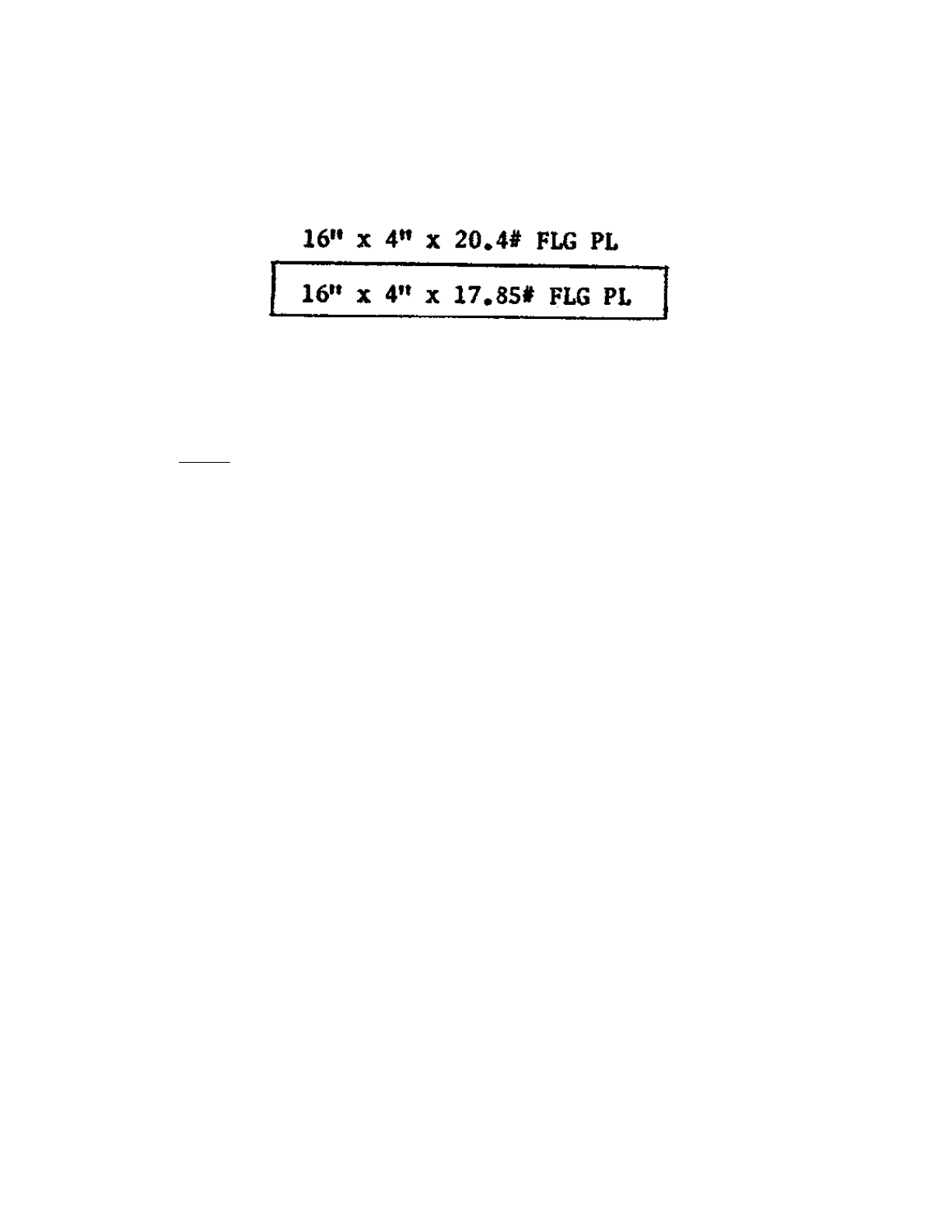
acceptable special coatings have been applied. In all such cases, the approved hull structural
plans clearly indicate such reduction by showing, for each plate and structural shape, both the
required tabular scantling and the permitted reduced scantling. For example, a structural shape
would be indicated on the plan as follows:
Normally, painting of the hull structure has not been the subject of Coast Guard requirements.
However, in the case of vessels which have been allowed to have reduced scantlings on the basis
of special coatings, it is a valid concern of the Coast Guard inspector to insure that such coatings
are maintained. If corrosion has occurred, evaluation of the degree should be referred to the
required tabular scantling and not to the as-built scantling.
(F) HIGH STRENGTH STEELS
1) The use of high strength steels in some recently built ships introduces new problems
which must be carefully considered when evaluating structural renewals or repairs. These
steels offer significant advantages in saved weight and their use permits thinner sections
to be used in highly stressed areas which would otherwise require excessively thick
sections of conventional ship steel. However, the thinner plating and sections of high
strength steel are not as forgiving of poor design as the heavier sections of mild steel.
Special attention must be paid to the possibility of buckling and detailing in the design
and careful fabrication becomes a must. Also special procedures are required for welding.
These are discussed in Section W.
2) Structural renewals in areas where high strength steels have been used must be made with
the same high strength steel. In some cases, an equivalent grade may be substituted. Also,
repairs to high strength steels must be made in accordance with the specified procedures.
A problem arises because high strength steels are not visually distinguishable from
ordinary ship steel. The use of such steels should be indicated on the vessel's Certificate
of Inspection and by the entry "special material" in column (4) in the "RECORD" of the
American Bureau of Shipping. Further, both the American Bureau and the Coast Guard
have requested that vessels utilizing high strength steels in their construction shall retain
on board structural drawings identifying the special steel, indicating where it is used and
specifying, in detail, the required welding and fabrication procedures.
3) In any larger vessel built since 1964, renewal or repair in way of the main hull girder
should not be undertaken without first examining the vessel's approved structural plans to
confirm if high strength steels were used. If so, every care must be exercised to use the
correct steel for renewals and to adhere to the specified procedures for both renewals and

- 9 -
repairs. It is well to note that there is no such thing as a "minor" repair where high
strength steels are involved. Further information on the use of high strength steels is
available from the Commandant (MMT) or field (mmt) office.
(G) ALTERNATIVES
In some instances, owners may desire to install supplemental structural reinforcement rather than
replace deteriorated material. This may be feasible, but since it constitutes a modification of
design, plans detailing the proposed changes should be approved before the work is carried out.
(H) DECK PLATING
Deck plating comprises a highly stressed portion of the hull girder and is of critical importance to
the longitudinal strength of the vessel. Accelerated corrosion may be expected in the deck
because it is subject to mechanical abuse from deck cargo, hatch beams and repeated scaling.
Also, it is always exposed and frequently awash. Because of this, the deck plating, especially in
the midship's half length, should be carefully examined for cracks, leaks, or signs of excessive
wear. The corners of hatch or other deck openings, the corners of deck erections, pads, or other
items producing discontinuities or hard spots should be examined for evidence of cracking.
Whenever practicable, the detail concerned should be eased and made less abrupt when repairs
are made. In the case of riveted construction, special attention should be paid to the riveting of
butts. Discovery of working or loose riveted butts calls for prompt corrective action. This may be
evidence of cracking at the rivet holes not yet sufficiently extensive to extend beyond the rivet
head. Cracking of the plate will, in general, call for replacement of that portion of the plating.
Buckling of deck plating is uncommon; however, the use of thinner high strength plating
increases the likelihood. Any such buckling can seriously impair the strength of the vessel and
calls for corrective
(I) DECK LONGITUDINALS
In tank vessels the corrosive deterioration of deck longitudinals may be much more rapid than
that of deck plating. These longitudinals are necessary to support the deck plating so that it can
carry local hydrostatic loading, to provide panel stiffness to the deck plating so that, as a part of
the hull girder, it can carry compressive loading without buckling, and also to directly contribute
to the hull girder stiffness and strength. Because the relative importance of these factors may be
different when dealing with different designs, it is very difficult to lay down any generally
applicable wastage limits. However, for the usual proportions of longitudinals to plating and
usual spans of a tanker of about T2 size, deterioration of some deck longitudinals up to a
maximum of about 49 percent or about . 18" wastage, whichever is the lesser, may be accepted
provided the average deterioration is not more than about 30 percent or about .14" wastage,
whichever is the lesser. For a single voyage, maximum deterioration of some longitudinals as
high as about 50 percent or about .22" wastage has been accepted. The above applies to
longitudinals fabricated from structural shapes such as inverted angles or T bars. In the case of
flat bar longitudinals, the strength of the combined deck plate and longitudinal is critical in
compression. Consequently, not more than about a 20 percent corrosion allowance should be

- 10 -
permitted. Additionally, flat bar longitudinals should be faired or replaced if they are distorted or
buckled to any degree. In the case of river tank barges not carrying any deck cargo, general
deterioration of deck longitudinals up to about 40 percent may be accepted. Since the obvious
necessity for maintaining oiltightness does not apply to the rake ends, they tend to be neglected.
This should not be permitted since the rake ends provide the major buoyancy of the vessel and
are, therefore, vital to seaworthiness.
(J) KEEL PLATING
In recognition of local strength factors and also the additional corrosion to which keel plates are
subject as a result of being unavailable for painting when sitting on keel blocks in drydock, keel
plating is normally of greater thickness than the balance of the bottom plating. Taking account of
the fact that a large part of this extra thickness may be regarded as an additional corrosion
allowance, it is generally satisfactory to defer the replacement of keel plating until the wastage is
somewhat more than would otherwise be considered acceptable. In determining the amount of
such extension, consideration should be given to the condition of adjacent "A" strake(s). If the
adjacent plating is in good condition and does not require replacement, the keel plating may be
accepted provided the effective remaining thickness is not less than approximately 75 percent of
the original thickness of the adjacent strakes and provided it is not buckled or otherwise
damaged. If the adjacent plating is wasted so as to, itself, require replacement, it is generally
wise to replace the keel plating even though it may be wasted no more than about 25 percent of
its thickness.
(K) BOTTOM PLATING, INNER BOTTOM PLATING AND BOTTOM INTERNALS
1) The bottom plating complements the deck plating as the lower flange of the hull girder.
As well as sustaining a major portion of the hull bending moment, it is subject to
increased stress due to water pressure. Its strength may be reduced either by general or
localized corrosion and by buckling. In view of the prime importance of this plating, the
maximum average reduction in thickness to be permitted in about the midships half-
length is about 20 percent. If the wastage exceeds this amount the plating should be
renewed. Alternate measures or means of reinforcement can be considered but since they
would constitute a major change in the design of the vessel, plans for same should be
submitted for approval to the field (mint) office or to the Commandant (MMT). If after
consideration of the bottom shell plating with regard to the main longitudinal strength
there should remain local areas or plates requiring attention, these may be dealt with on
the basis of a maximum average wastage of about 25 percent from original, provided the
plates and supporting structure are otherwise in satisfactory condition. Welded butts
which exhibit excessive wastage (grooving) as compared to the balance of the plate
should be rewelded after excavation to sound metal,
2) Joggled lapped seams and butts are particularly prone to excessive local deterioration
because of the flexing which may take place at such joints and because they provide a
pocket in which corrosion may develop. Accordingly, when inspecting plating containing
joggled lapped joints, it is important to check the condition of the joint itself and

- 11 -
particularly the plating thickness in way of the joggle. Renewals should be in accordance
with Section IV (B) of these notes.
3) Unfair or set-in plating is common forward. A fair degree of deformation of the hull
plates in the forward portion of a vessel ordinarily may be accepted without resulting in
serious impairment of structural strength. However, for transversely framed ships, severe
buckling or set-in condition of bottom plating within approximately the amidships half
length can seriously impair strength. In general, the greater the athwartship extent of
buckling the greater the impairment in hull strength. Any appreciable buckle of sufficient
athwartship extent to cross a center vertical keel or inner bottom girders is serious. Such a
buckle should be corrected by replacement of plating and the buckled portions of girders.
If there is no evidence to indicate the buckle was caused by grounding or other excessive
local loading, or is associated with excessive wastage, it may be an indication of need for
providing additional stiffening. In such instances, the Commandant (MMT) or field
(mint) office should be advised of the circumstances and proposed corrective measures.
Buckles of shorter athwartship extent may also require correction, depending upon the
depth or height of buckles, the number of buckles, and their relative locations. For
instance several bottom buckles within the same frame space are more serious than the
same number of the same size buckles distributed in a random manner. Localized
transverse bands of accelerated corrosion or grooving may be found in association with
buckles. These are indicative of localized excessive stress which experience indicates
may lead to cracking. Consequently, plating replacement may be called for even though
the deterioration may be less than 25 percent. In such case it is usually sufficient to
replace less than a full plate.
4) In the case of riveted construction, bands of stress corrosion may be observed, mostly
immediately adjacent to the riveted lapped butts, even where the plating surface is
generally quite fair. Experience has shown that cracking develops in these areas. Since
such cracks are in primary hull girder material, their occurrence must be regarded as a
very serious matter. Where zones of serious corrosion are noted, appropriate preventive
action in the form of plating replacement should be taken before any actual cracking
develops. In making such replacements, as in the case of welded construction, renewal of
less than a complete plate is acceptable if the condition of the balance of the plate is
satisfactory. The butts of such renewal inserts should be flush welded, care being taken to
insure 100 percent penetration. Originally riveted seams should be riveted, with sufficient
existing riveting adjacent to welds released and re-driven to insure 100 percent sound
riveting.
5) Tank tops are considered in the computation of scantlings for load line assignment both
by ABS and the Coast Guard and must of necessity be maintained in reasonable condition
consistent with their inclusion in the section modulus. Apart from the function of the tank
top and the double bottom internals in contribution directly to the section modulus, there
are two other structural functions which are equally important. First, without support by
the bottom transverses and longitudinals, the bottom plating has insufficient rigidity to
carry compressive loading and tends to buckle when the vessel is subjected to a hogging

- 12 -
bending moment. Secondly, the entire bottom structure has the function of resisting water
pressure when the vessel is in ballast and of bearing the weight of cargo when loaded. It
must be maintained in efficient condition to safely perform these functions.
6) A moderate amount of buckling of tank tops is acceptable provided buckling is confined
to the plating between transverse and longitudinal girders. Fairness of transverses and
girders may be checked by sighting or use of a taut line along the frame and girder lines.
If floors or girders are found to be appreciably deformed or cracked they should be
repaired or replaced. In doing such work, obvious defects such as sharp cornered or
raggedly cut lightening holes or other cut-outs should be made fair. Buckling of floors or
girders not associated with grounding or other external damage may be an indication of
structural weakness and need for structural modification or reinforcement, in addition to
repair. In riveted construction, loosening and failure of the riveting within the double
bottom may be observed. It is apparent that once the fastenings begin to fail, the stress
levels and corrosion rates in adjoining structure increase rapidly. The practical solution to
this problem is the early detection of the failing fastenings and the timely and adequate
replacement of these fastenings in order that the existing material in the vessel can be
made to perform to its capacity. The old adage that "a stitch in time saves nine" is
certainly applicable here.
(L) SIDE PLATING
In the side plating the strake "between wind and water" is an area which is highly susceptible to
corrosion. The maximum general wastage is to be expected in this area. Also, serious localized
corrosion may often be encountered in way of overboard discharges and scupper openings. The
latter may usually be repaired by the use of insert plates rather than by plate renewals. Suitably
attached wastage doublers may be used on sound plating as a means of protection.
(M) LONGITUDINAL AND TRANSVERSE BULKHEADS
Cargo hold bulkheads are usually not troubled by excessive corrosion except along the lower
boundaries and in way of bilge wells. Such corrosion is a local condition and should be repaired
by the use of insert plates or well attached lapped plates if sufficient material remains for proper
installation. In the case of the longitudinal and transverse bulkheads in a tankship, especially
where light products have been carried, corrosion is to be expected. Wastage up to about 35
percent may be accepted provided there is no evidence of deformation when subjected to a
hydrostatic test. The top strake of bulkhead plating in a tankship is usually made heavier in
anticipation of the increased corrosion to be expected in this area which is usually wet but not
submerged. Therefore, when referred to the original scantling, an increased allowance for
deterioration may be permitted. Applying a 35 percent wastage to the original scantling of the
next to topmost strake will serve to establish the minimum thickness acceptable in the topmost
strake.

- 13 -
(N) FRAMES, BEAMS AND STIFFENERS
Generally the flanges and portions of the webs next to the flanges are more highly stressed, more
subject to mechanical damage, and corrode faster than the balance of the member. If excessive
wastage has occurred but is limited to the flange and outer portion of the web, cropping of the
defective section rather than complete renewal may be permitted. Details on this are included in
Section IV. The use of short lengths of flat bar welded in way of deteriorated material is not an
acceptable repair. Full length fiat bar doublers may be satisfactory in some cases but this
represents a change in design so the installation should be made in accordance with an approved
plan. Notwithstanding the above, flat bar doublers are never acceptable on internals within the
tanks of a tankship because of the danger of gas entrapment. Often times, projecting frames or
beams are deformed due to hook pulls, damage by cargo, etc. Such conditions, if they are
scattered and not serious to the extent that the members are torn or broken loose from their
fastenings, may be permitted to remain until there is other work required in the area. However,
this principle would not apply to structural columns.
IV. NOTES ON REPAIRS
(A) FRACTURES
1) Fractures in hull plates, etc., usually start in localized, highly stressed areas. In the
preliminary inspection, the first thing to be determined is whether or not the fracture
started in a notch or sharp angle (stress raiser), and if it did, to eliminate this feature.
2) Major fractures. When major fractures occur and where considerable material is to be
removed and new plates, frames, etc., are to be inserted, the repair may involve
appreciably more restraint and less favorable welding conditions than for new
construction. The type of repair to be made and welding procedure to be used should be
carefully evaluated.
3) Cracks. Cracks in the deck or in the bottom within about the admidships half length and
which originate in structural discontinuities will frequently require the fitting of a suitable
repair insert in order to minimize weld restraint in the local area of stress concentration.
Cracks which have opened too far or are too irregular to permit satisfactory weld
preparation, or which are located so that access is insufficient for producing sound, full
penetration welds, also call for the fitting of inserts. Evidence of deterioration or poor
quality of the fractured plate are additional reasons for plate replacement.
4) As previously noted, localized bands of accelerated corrosion should ordinarily be taken
as evidence of such deterioration and the affected portion of plating replaced. Where
none of the foregoing conditions exist, the crack may be repaired by welding without
replacement of plating.
5) In repairing cracks which do not involve steel replacement, the following procedure
should be followed:

- 14 -
a) Locate the ends of the crack, and approximately two plate thicknesses beyond the
end, drill a hole to prevent its extension. The use of dye penetrant or other NDT
method is desirable to locate the ends of the crack or to insure the crack does not
extend beyond the holes. The diameter of the drilled hole should be about the
same as the plate thickness. Then, V out the crack by chipping or gouging to an
accepted edge preparation for welding plates of the particular thickness involved.
b) Gas free, remove ceiling, etc., as necessary to provide full access to both sides of
the crack. Thorough inspection of both sides of the crack should always be carried
out.
c) After V-ing out, if a crack has a root opening too wide for closing with the first
bead, do not draw the edge of the plate together by means of a steamboat ratchet
or other means preliminary to welding. Instead, build up the groove with light
beads until a groove of usual proportions is obtained or use a backing strip.
Backing strips should be removed followed by back side chipping and welding.
d) Where the crack in the plating crosses stiffeners, framing or girders, the welds
connecting these members to the plating should be released. This should be done
by burning through the weld for a distance of at least 6 inches on each side of the
crack before welding of the crack is commenced. In way of gunwale or hatch side
assemblies, it may be desirable to increase the length of release.
e) If the crack extends into the framing member, it should be suitably prepared and
welded. If the resulting butt is welded after the plating or poor accessibility exists,
the butt in the frame should be smoothly scalloped out adjacent to the plating.
f) Special care should be taken in the repair of surface cracks. Care should be taken
that the defect is completely removed by grinding or other suitable means. In that
such a procedure may easily mask cracks by the "peening" effect, the use of a
NDT method such as magnetic particle may be useful in detecting any remaining
subsurface defect.
(B) REPLACEMENT OF AND WORK ON SHELL AND DECK PLATING
1) The following precautions apply to repairs or alterations on both riveted and welded
hulls:
a) Sheer strake. The sheer strake, insofar as practicable, should be kept clear of
welded fittings. Where there is no alternative but to make attachments in this
region, the attachment should be suitably faired with curved brackets, as
applicable, and at least 150°F. preheat should be maintained during welding.
However the use of preheat may ordinarily be omitted if low hydrogen electrodes
are used. The upper edge of the sheer strake should be fair and smooth, i.e., free
of notches, nicks, and cuts, weld craters, and any irregular edge burning. Because
of the change in ship steel requirements which became effective at that time, the

- 15 -
foregoing precautions are particularly applicable to ships built prior to 1947.
b) Stringer plate. Insofar as practicable the stringer plate should also be kept free of
welded attachments. .
c) Welding of deck fittings. Where heavy deck fittings, such as chucks, bitts and
cleats, are to be welded to the strength deck, pre-heat of at least 150°F. should be
employed during welding or low hydrogen electrodes should be used. Such heavy
fittings should only be installed in accordance with approved plans. Ends of deck
fittings should be kept well clear of deck butts and seams. When a number of
fittings are installed on deck, positioning them in a direct line athwartships should
be avoided. Also, if they are required to be in a longitudinal line, there should be
sufficient interval between each so as to avoid creating areas of high stress
concentration in the plating between the fittings.
d) Replacement of plates having joggled lapped seams and/or butts should be made,
whenever possible, with flush seams and butts. A typical method is shown on the
following page:
- 16 -
(C) INSERT PLATES
In welded construction, repairs involving less than a full plate should generally be made by
means of an insert plate installed in accordance with the following principles:
a) While less than complete plates may be replaced, the lines of cut and new welding
should, as far as practicable, lie in existing lines of welding. Inserts should
ordinarily cover at least one frame space.
b) The existing plate should be cut back to good material. (No less than 3/4 thickness
of plate being inserted.) The existing plate edge and the internals in way of the
cutout should always be examined before the insert is installed.
c) The shipfitting and plate edge preparation should be such that welding grooves of
proper proportions are provided so that acceptable welds can be made.
d) The weld metal of intermediate passes on butts and seams of restrained insert
plates may be peened. The finish pass should not be peened but may
advantageously be made using low hydrogen electrodes.
- 17 -
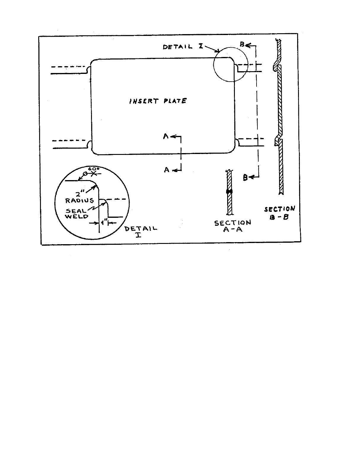
e) To minimize locked-in stresses when installing an insert plate, it is necessary to
ease the restraint imposed by the surrounding structure. First, holes should be
drilled as shown below to reduce the likelihood of cracks occurring at the ends of
the slots. The adjacent plating should then be slotted as shown below. Butts 1 and
2 can be welded first so that the slots can serve to distribute the shrinkage
somewhat rather than concentrating it at the immediate boundaries of the insert
plate. Rounding the corners of the insert plate, not in way of existing seams or
butts, is an acceptable alternative.
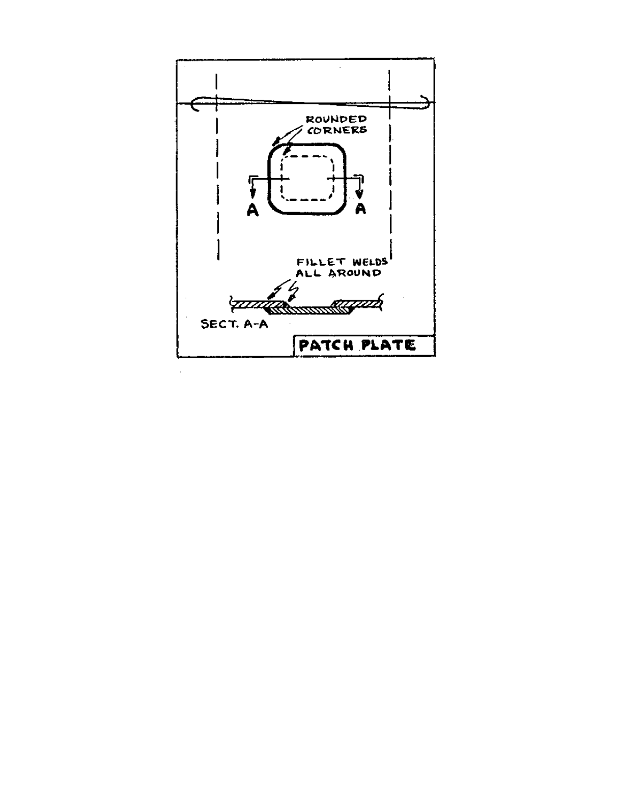
f) In certain cases, a welded lapped patch plate may be used in lieu of an insert plate
for the permanent repair of small damaged areas which lie wholly within an
individual panel of plate. However, except for temporary repairs, their use should
not be permitted in the strength deck, bottom or shell plating. Patch plates are also
inadvisable in areas of high corrosion. In making the installation, the old plate
should be cut away to a sufficient thickness of sound metal so that the existing
metal at the edge of the patch is at least as good as would be required if an insert
were used. If the opening required to achieve this exceeds that appropriate to the
use of a patch plate, an insert plate should be used. Patch plates should be
continuously fillet welded both inside and outside. In order to reduce heavy stress
concentrations in the vicinity of patch plates, such plates and the holes which they
cover should have their corners rounded to a radius at least equal to one eighth of
their transverse dimension or three inches whichever is the greater.
- 18 -
(D) WELDED DOUBLER PLATES
1) A welded doubler plate is not, in general, considered suitable as a permanent repair
measure for the main hull girder. Its use does not insure continuity of strength which is
achieved by the installation of an insert plate in the same location. Also, when a doubler
is attached to deficient plating, its very presence creates a discontinuity which may
induce rather than prevent a structural failure. Additionally, where doublers have been
used, they tend to proliferate as randomly placed patches which often serve only to cover
up the deficiencies which would otherwise indicate the true condition of the hull.
2) Doublers may properly be used to provide local reinforcement at hatch corners,
overboard discharges, seachests, mast or kingpost foundations, etc. They may also be
used in accordance with approved plans, in the form of strapping fitted to increase the
hull girder strength and stiffness. Where so used the plating to which they are attached
should be in good condition to insure efficient attachment, by fillet welding along the
edges. Plug welding, in the body of the doubler, can be used. The corners of the doubler
should be tapered and well rounded.
3) Doublers may be accepted in non-strength areas where their purpose is essentially to
restore watertight integrity and local strength. Such areas include:
a) deck plating well inboard between cargo hatches

- 19 -
b) house tops and superstructure decks except the first deck above the main deck in
vessels with long superstructures
c) forecastle decks and poop decks limited to approximately the forward or after
one-tenth length of the vessel
d) platform decks
4) Even in these locations, doublers should not be permitted where special local strength is
required. For example, the plating forming the house top of a small deck house is not
involved in basic hull strength. Repair by doubler would be perfectly acceptable if the
deck house served as a bosn's locker or the plenum of a ventilation system. However, if
the house top plating tied together the framing intended to fix the position of a mast or
kingpost, a doubler patch would not be permissible. Another example in the same
category is the superstructure deck plating in way of a lifeboat installation.
5) When a doubler is deemed appropriate and is installed over a crack, the ends of the crack
should be drilled and, if possible, the crack should be veed and welded.
6) On vessels without double bottoms operating on protected waters or in other similar
circumstances on such vessels, doublers may be accepted for repairs in way of engine or
boiler rooms where it would be necessary to remove heavy equipment, etc. in order to
provide access for plating replacement. However, in such cases, care should be taken that
existing plating has enough thickness for efficient attachment. -
7) Doublers on tank vessels in way of cargo or fuel tanks are a special problem. The
interface between a doubler and the plate beneath can constitute a gas pocket which is
hazardous and completely inaccessible to gas-freeing procedures. Doublers should not be
permitted in such locations except as detailed on approved plans.
8) Plan approval is usually not necessary for installations made in accordance with
paragraphs (3) and (4) above. However, a record of each installation, including its size
and location, should be maintained in the vessel's inspection file.
(E) CROPPING AND RENEWING
1) In the case of structural members such as frames, beams, stiffeners, etc., it is a practical
repair measure to crop out the distorted or wasted section of the member, the outer flange
for example, and replace with new material. Where this method is used, the following
conditions should prevail:
a) There should be sufficient material in the remaining portion of the member to
permit sound attachment of the new metal.
b) The new portion should be in good alignment with the adjoining old portion.
Particular care should be exercised in this regard in way of flanges.
c) There should be sufficient clearance to permit the making of good welds. If this is

- 20 -
not the case, the member should be renewed,
d) If the attachment of the member to the adjoining plating is by riveting, the joint
will have to be checked for tightness and corrected as necessary after completion
of welding.
V. WELDING
(A) GENERAL
Section 26, Parts I and III of the American Bureau of Shipping Rules for Building and Classing
Steel Vessels contains the requirements and instructions for the production of acceptable hull
welds and the qualification of welders. These rules are not repeated here because they are
available to and should be used by inspectors engaged in construction or repair work. Some
points which require special note are discussed in the following paragraphs.
(B) WELDERS
In view of the importance of obtaining sound welds in repair work, normally only welders
qualified by the Coast Guard, the American Bureau of Shipping or the Naval Ships Systems
Command (Navy Department) should be employed. In some cases, qualification by other
government agencies or fabricators may be acceptable. Cases of this nature should be referred to
the Commandant (MMT) for resolution.
(C) STEEL
1) Steel plate and shapes which are to be welded should meet the applicable requirements
for structural steel for hulls as set forth in Section 39 of the American Bureau of Shipping
Rules for Building and Classing Steel Vessels. Half rounds, rounds and bulb bars are
frequently produced from Bessemer steel which is not permitted by American Bureau of
Shipping Rules due to the likelihood that such steel may be very notch sensitive at
ordinary operating temperatures.
All ship steel, including the above items, must be made by the open hearth, basic oxygen,
electric furnace or such other process as may be specifically approved. The ends of half-
rounds and bulbs should be kept clear of existing structural discontinuities. Half-round
installations which disturb the smooth, unnotched edge of the sheer strake should be
avoided. High strength steels require very special handling during fabrication. Great care
must be exercised in adhering to the procedures recommended by the steel manufacturer,
in the care and use of the correct welding electrodes, and in the proper identification of
the steel. The usual shipyard practices suitable for working with conventional ship steel
are not adequate when it comes to high strength steel. Among the more important reasons
for this are the following:
a) Steels look the same, but when used in the design of a ship, much greater loads
are imposed on the special steels; loads which probably could not be sustained if

- 21 -
conventional steel was substituted by mistake.
b) Welding electrodes which are satisfactory for conventional steel would not
provide strength, in way of the welded connection, equivalent to the strength of
the plates joined. In most cases, low hydrogen electrodes are recommended for
welding high strength steels in order to avoid underbead cracking. -
c) In some high strength steels; for example, the quenched and tempered steels, a
heat input during welding which would be acceptable for conventional steel,
would drastically reduce the toughness of the special steel in the heat affected
zone (HAZ).
d) Also, in some of these steels, the installation of temporary clips or even arc strikes
on the plate can have a serious, detrimental effect. -
2) In view of the above, renewal or repairs involving high strength steels should not be
undertaken without recourse to plans and procedures which have been approved for the
specific installation. Further information on the welding of high strength steel is available
from the Commandant (MMT) or the field (mmt) office.
(D) FILLER METAL
1) Electrodes should be suited to the steel to be welded. Except when special steels are
involved or specific electrodes are indicated on approved plans, the welding electrodes
should be among those listed in the current American Bureau of Shipping approved list,
"Approved Welding Electrodes Wire-Flux and Wire-Gas Combinations."
2) This list is distributed to all Marine Inspection Offices by the Commandant whenever
new issues are published. It is to be noted that most of the approved welding electrodes
are listed in Equipment Lists, CG-190, but this listing will be discontinued beginning
with the 1968 edition. Electrodes should be kept dry while in storage. Where low
hydrogen electrodes are used, it is especially important that they be de-hydrated before
use. Otherwise, moisture picked up from the atmosphere alone without any direct wetting
may result in very faulty welds.
(E) EDGE PREPARATION
The preparation of the edge of the base metal before welding depends upon the thickness of the
plate and the design of the joint. The requirements are specified in Section 26 of the American
Bureau of Shipping Rules. The following are some points which require special attention:
1) Rough or irregular preparation of the edge should not be accepted.
2) The dimensions of the root opening should be within the specified tolerances. Excessive
root face, insufficient root gap, or insufficient bevel angle will result in poor penetration.
Too wide a root gap will result in difficulty in making a satisfactory root pass unless one
face of the joint is first built up by welding or a backing strip is used. All of these
- 22 -
deficiencies are readily apparent if the fit-up is examined before the welding is
commenced and all are correctable.
3) The surface to be welded should be clean and dry. This includes both the base metal and
previous beads of welding. A clean surface is one free of dirt, slag, oil, rust, scale, or
paint.
(F) WELDING SEQUENCE
In most repair work locked-in welding stresses cannot be avoided. However, they can be
minimized if some attention is given to working in accordance with a planned welding sequence.
In general, this must be left to a welding engineer. But, when major repairs are undertaken, the
inspector should ascertain that a welding sequence has been prepared and he should check to see
that it is followed on the job. Some
of the fundamental considerations in this regard are as follows:
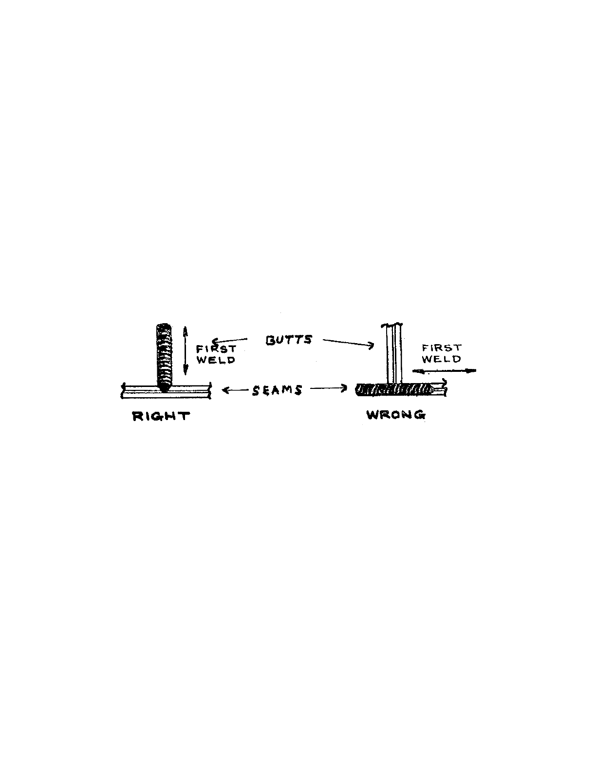
1) It is poor practice to weld across an open butt.
2) Where extensive work is required on both sides of the vessel, it is better practice to have
the welding progress simultaneously on both sides rather than to complete one side
before starting the other.
3) In general the order of welding should be such as to allow the maximum freedom for
contraction of the weldment. For example, it would be poor procedure to fix both shorter
edges of a plate before welding the longer edges.
4) Temperature is an important factor in welding. Where welding is done at temperatures
appreciably below freezing, pre-heat and/or shelter should be provided to reduce the rate
of chilling. More caution in this regard is necessary when welding on thick plating than
on thinner plating.
For ordinary thicknesses and temperatures not far below freezing, work within a ship or on a
ship's bottom within a graving dock may usually be considered as sufficiently sheltered.
(G) PROCEDURE
1) Besides proper shipfitting and edge preparation, there should be careful alignment of the
- 23 -
structure. Local eccentricity in butts of intercostal longitudinal beams, girders, and
bulkheads attached to strength deck and shell is conducive to service cracking. The webs
of such members should be carefully aligned on both sides of the interrupting (transverse)
structure before welding, and changes of girder depth and flanges occurring at the
interrupting section should be provided with transition fairing.
2) Tack welds which are used to position the weldment in the fit-up should be chipped out
before making the final weld. Frequently, they have been overstressed and may contain
sub-surface cracks. The welding machines employed should be adequate for the job, in
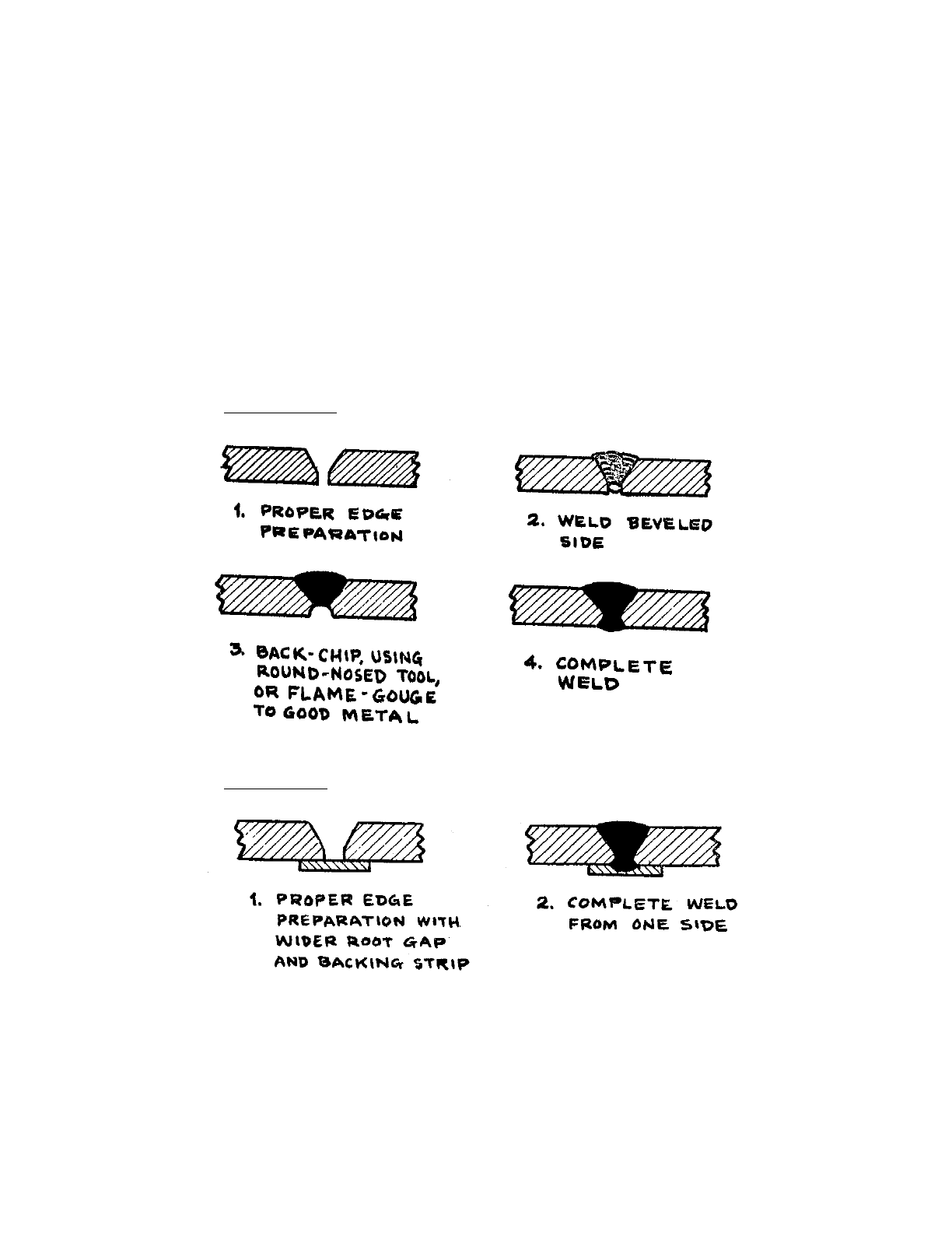
good condition and operated at the correct setting for the work at hand. Butt welds,
except in very thin plates, call for back-chipping with a round-nosed tool or by means of
flame-gouging in order to insure complete penetration. The use of a backing strip, flux
back-up, etc., are satisfactory alternatives.
Ⅰ Back Chipping
Ⅱ Backing Strip
(H) WELDING DEFECTS
1) Particular attention is called to weld deficiencies which can occur if correct procedures
are not followed. These weld deficiencies can and do lend to cracking of the main hull
girder of the vessel and are about the most effective crack initiators known. The

- 24 -
destructive potential of the deficiencies often lies dormant for protracted periods while
awaiting the necessary conditions of temperature and/or service stress magnitude to
trigger a crack which instantaneously propagates into a serious hull failure. Such failures
can occur under fairly moderate stresses, arising from sea action or from cargo
distribution alone, on a cold winter day.
a) Sub-surface weld defects in butts and seams which include interpass weld bead
cracks, slag inclusion, incomplete penetration and lack of fusion must be avoided.
b) Slugged welds. Slugged welds involve laying welding rods, cable, bolts or other
extraneous material in a welding groove and then welding over it. Such a
procedure obviously creates a serious cavity in the heart of the weld which is not
detectable from surface appearance. Supervisors and workmen who have been
well informed as to the critical nature of such a condition are the best protection
against slugged welds. Welders turning out very high footage should have their
welding subjected to radiographic examination as a precaution against "slugging."
c) Caulking of leaky or cracked welds. Caulking or peening in no way reduces the
crack initiating properties of a defective weld nor does it reduce the liability of an
existing crack to propagate further. Such an operation only serves to "conceal"
and thereby "build” into the vessel a potential source of serious structural failure.
Accordingly, all peening or caulking of leaky or cracked ship welds should be
prohibited. Leaky or cracked welds should be chipped out and re-welded.
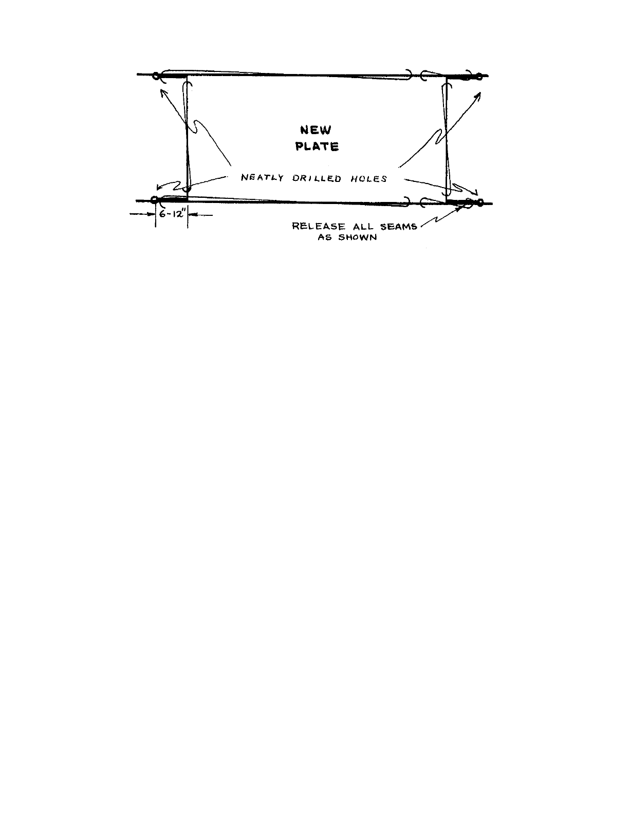
d) Square corners. Welding into or around square corners, such as can occur in the
installation of insert and doubler plates, should not be permitted for attachments
to shell, strength decks or tank tops. Such square corners should be rounded to a 3
inch minimum radius. Corners of openings should be rounded to the largest
practicable radius, generally not less than 1/8 the transverse dimension but not
ordinarily more than 24 inches. Cuts should be made either by guided burning or
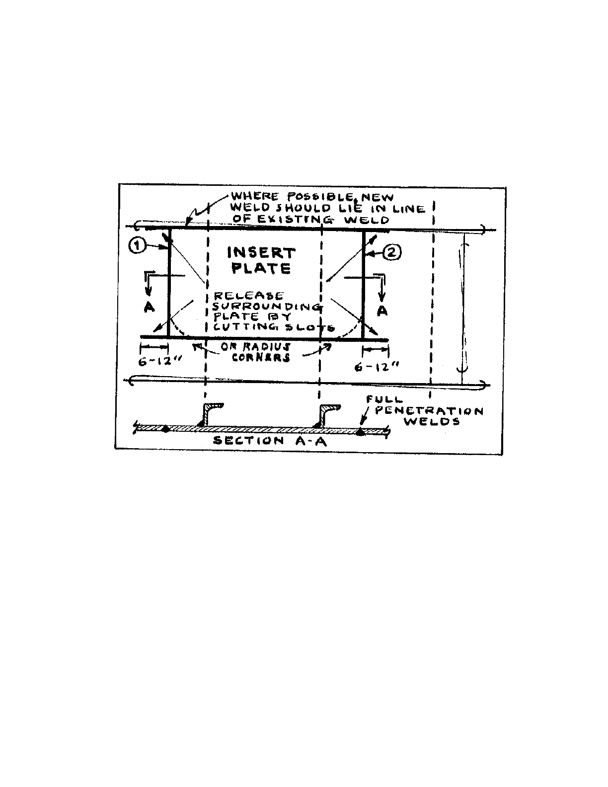
should be ground to a fair smooth contour. An exception to this is the welding of
an entire plate section. Generally, the corners are not rounded but the seams in the
adjacent plates are released as shown in the following sketch to minimize locked-
in stresses and then rewelded in suitable sequence. Holes drilled as shown prior to
releasing the adjacent plate will minimize the likelihood of cracks occurring at the
ends of the slots.
- 25 -
e) (e) Undercut welds. Undercut butt and seam welds of shell, inner bottom and
strength deck, or undercut fillet welds attaching structural members thereto,
should be avoided. This is particularly important for fillet welds near or at the end
of discontinuous longitudinal members, such as bilge keels, tanker longitudinals,
deck clips, or foundation members. Undercutting in these locations has
contributed to complete hull girder fractures.
f) Arc-strikes and light beads of welding. Arc-strikes and light beads of welding
should be avoided on the surface of strength deck, shell or tank-top plating, due to
quench effect with possible subsequent crack stimulation. Arc-strikes produce
hard, brittle metal locally, containing microscopic cracks. It is recommended that
such areas be chipped out and re-welded using a pre-heat of at least 150° F.
g) Projections or cavities. Very often pads or lugs are welded to plates for the
purpose of jacking the plates into alignment and afterwards are knocked loose
with a sledge. Any projections resulting from knocking off the lugs should be
chipped off and ground fair if necessary. If there are any cavities these should be
welded flush.
2) Slugging, included slag, or submerged cracks cannot be determined by the surface
appearance of welds. These defects, however, can seriously reduce the strength of a
welded joint and can provide the starting point for serious fractures. Section 26 of the
American Bureau of Shipping Rules for Building and Classing Steel Vessels provides for
radiographic or equivalent inspection of hull joints at important locations. Since any
joints in the hull, including the upper decks within approximately at least the middle half
length may be regarded as important, this rule is considered to provide a basis for
requiring random spot checking of hull welding by means of radiographic or ultrasonic
techniques. Such spot checking should be accomplished to the extent determined
necessary by experience in checking welding in the yard concerned. Yards should keep a
record of the work performed by each welder. Any welder found to be deliberately
slugging welds should be disqualified and may be subject to criminal prosecution. -

- 26 -
3) When welds are checked by a non-destructive testing method, such as radiography, the
question often arises as to the proper standard to apply for a rejection or acceptance
criterion. Slugged welds, of course, give a gross defect indication and there is no question
as to the non-suitability of such a weld. Other welding defects such as slag inclusions,
porosity and subsurface cracks require some judgement as to what constitutes an
unacceptable weld. There is no simple answer. In some cases, such as a main strength
highly stressed joint, a very rigid standard would be proper. In other cases, an evaluation
of the design and the type of stress applied might indicate a large margin of safety exists
and the acceptance criteria can safely be set lower, The following information sources
offer guidance:
SSC-177 "Guide for Interpretation of NDT of Welds in Ship Hull Structures"
prepared by the Ship Structures Committee
IIW Pamphlet "Radiographs of Welds"
ABS circular No. 145, Guide for the Radiographic Inspection of Welds
ABS Circular No. 40, Magnetic Particle Inspection
SSC-177 applies only to hull welding and therefore the requirements are not as stringent
as for pressure vessels.
VI. RIVETING
(A) GENERAL
The renewal of deck and shell plating is best accomplished from an overall structural viewpoint
by replacement in kind, (i.e.) riveted replacements in riveted hull is to avoid hard spots or points
of high stress concentration in an otherwise less restrained hull structure. However, riveting is
becoming increasingly difficult and costly. Hence, it becomes necessary to make welded repairs
to riveted ships. Extensive experience and tests indicate that the steel in the existing riveted ships
may be more sensitive to brittle fracture initiation and propagation, when welded, than is
shipbuilding steel presently being supplied under American Bureau of Shipping requirements for
Classes B or C hull steel. Because of this, the use of welding in the repair or alteration of existing
riveted hulls should be limited as follows:
1) Shell and deck seams involving existing plating thicker than 1/2" should ordinarily not be
welded.
2) As previously noted, flush butts between new and existing strakes of shell and deck may
be welded. Such welds must have full penetration.
3) Lapped butts involving the use of fillet welds should not be used. Welded lapped seams
may be used where plating is 1/2" or less in thickness.
4) For greater thicknesses, replacement should be as original or the design changed so that
- 27 -
butt welds can be employed. A typical method of doing this with in-and-out plating is
shown in the sketch below. For joggled plates, see Section IV (B) of these notes.
(B) HOLE PREPARATION
Where riveting is necessary and the rivet holes are punched, the holes should be reamed in order
to remove the excessively cold-worked material which can be a source of crack initiation. The
holes need to be reamed between 1/16" and 1/4" depending on the thickness of plate and the
diameter of the hole. In most cases a ream of 1/8" will be suitable.

- 28 -
(C) DETERIORATED OR MISSING RIVETS
The replacement of deteriorated or missing rivets, which were marginal in size in original
construction, with undersize bolts is unsatisfactory. However, upon approval by the Officer in
Charge, Marine Inspection, bolts may be used for emergency purposes if oversized and closely
fitted into oversized, reamed holes. Often the ringing of rivets by means of welding is proposed
as a repair measure for leaking or otherwise defective rivets. Rivets which do not completely fill
and are not firm and tight in their holes fail to effectively carry their share of the load, and
ringing with welding does not improve this situation. Accordingly, any ringing of rivets by
welding must be regarded as a temporary measure acceptable only where not more than a few
scattered frame or seam rivets are involved. Ringing of rivets by welding should not be permitted
in way of lapped or strapped butts, or for any riveting of deck plating outboard of the hatches.
The use of welding in building up the deteriorated points of otherwise sound rivets is
permissible, however, provided the corroded metal can be and is removed prior to the time that
the building up is done.
(D) LOCK PINS
Certain types of lockpins have been accepted as a substitute for hull structural rivets. Unless
lockpins are specified on an approved plan, they should not be used in repair applications
without consulting the Commandant (MMT) or a field (mmt) office. See NWIC 3-68 for further
information on this subject.
VII. OTHER INFORMATION SOURCES
Several NAVICS are published or in process of preparation on related subjects. An effort has
been made to avoid duplication of material; therefore, it will be necessary to consult the
appropriate circular when seeking information for materials or special processes not covered by
these notes. Examples of subjects covered elsewhere include:
1) Steels for Low Temperature Service (NVIC 7-67)
2) Tensile Fasteners (Lockpins) (NVIC 3-68)
- 29 -
VIII. NOMOGRAPH FOR PERCENTAGE OF WASTE IN STEEL PLATE
